
4046 PLL bassed A roulette wheel electronic circuit with explanation
The roulette wheel electronic circuit utilizes a 4046 PLL to achieve precise frequency control through its integrated VCO. The VCO is crucial for generating the timing pulses that dictate the operation of the circuit. The frequency modulation is achieved by adjusting the voltage at pin 9, allowing for dynamic control over the output frequency based on user input.
The phase comparators within the 4046 PLL ensure that the output frequency remains stable and synchronized with the desired frequency set by the external components R6 and C2. The source follower configuration aids in buffering the output to prevent loading effects that could alter the frequency characteristics. The Zener diode is employed to maintain a stable voltage reference, ensuring consistent operation across varying supply conditions.
Upon activation of switch S1, the circuit initiates the timing sequence, and the VCO produces pulses at the specified frequency. The capacitor C1 plays a vital role in the discharge cycle, providing a gradual decrease in voltage that influences the timing of the next pulse cycle when S1 is opened. This feature enhances the user experience by allowing the wheel to spin smoothly before resetting.
The 4017 decade decoder/driver is integral to the visual output of the circuit. Each output pin corresponds to a specific LED, which illuminates in response to the clock pulses received from the 4046 PLL. The design allows for flexibility in the LED configuration, enabling various visual effects that can enhance the aesthetic appeal of the roulette wheel setup. The use of only eight outputs simplifies the design while still providing sufficient representation for the game.
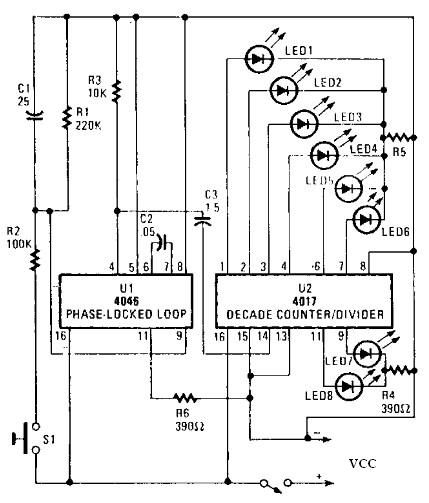
In summary, this roulette wheel electronic circuit combines frequency generation, timing control, and visual output in a compact and efficient design, suitable for various applications in gaming and entertainment. The modular approach allows for easy modifications and enhancements, making it adaptable for different user requirements.A roulette wheel electronic circuit can be designed using a 4046 PLL containing a voltage controlled oscillator or VCO, two phase comparators, a source follower, and a Zener diode that is used to produce a low-frequency, pulsed output of about 40 Hz. The VCO`s frequency range of this roulette wheel electronic circuit is determined by R6 and C2, wh ich can be altered by varying the voltage at pin 9. The rising voltage causes the frequency to rise from zero to threshold and remain at that frequency as long as SI is closed. When S1 of roulette wheel electronic circuit is opened, C1 discharges slowly through R1 to ground and the voltage falls toward zero.
The output of 4046 PLL at pin 4 is connected to the clock input of U2 which is a 4017 decade decoder/driver ( at pin 14 via C3). U2 4017 decade decoder/driver sequentially advances through each of its ten outputs (0 to 9) ”pins 1 to 7, and 9 to 11 ”with each input pulse.
As each output goes high, its associated LED is lighted, and extinguished when it returns to the low state. Only eight outputs are used in the circuit, giving two numbers to the spinner of the house. The circuit can be set up so that the LED`s lights sequence or you can use some staggered combination; the LEDs grouped in a straight line or a circle.
🔗 External reference
Related Circuits
A pH meter is a precise voltmeter that measures the generated voltage of pH electrodes. The demand for such a meter is significant. A pH meter operates by utilizing a combination of a glass electrode and a reference electrode. The...
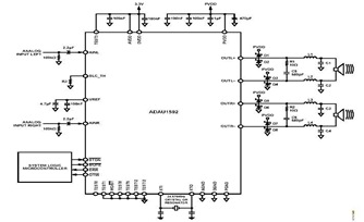
This is a typical stereo application circuit schematic of the ADAU1592, a 2-channel, bridge-tied load (BTL) switching audio power amplifier. The ADAU1592 can be utilized in flat panel televisions, PC audio systems, and mini-component applications. The ADAU1592 is designed to...
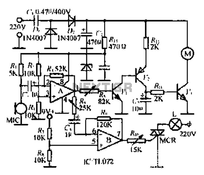
A microphone (MIC) is used to capture sound, which is then converted into a voltage signal. An operational amplifier (op-amp A) acts as a buffer; one output is directed to a motor drive circuit to control the motor's rotation...
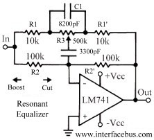
This topic discusses a resonant equalizer, which is a distinct type of circuit compared to the standard audio equalizer, although both achieve similar outcomes. The key difference is that the frequency responses of both the high and low frequency...
The following circuit illustrates the electronic diagram design for police and ambulance alarms. Features include simplicity and ease of assembly, as well as cost-effectiveness. This electronic schematic represents a basic alarm system intended for use in police and ambulance applications....
Camping today often involves various electronic accessories for daily activities or entertainment. Typically, a portable battery charger and a power inverter are used to ensure a well-organized campsite where both adults and children can comfortably use their electronic devices....