
Bass circuit diagram

The circuit design utilizes a fourth-order low-pass filter implemented through IC1-1, which effectively attenuates high-frequency signals while allowing low-frequency signals to pass through. The specified cutoff frequency of 70 Hz ensures that signals below this frequency are amplified, while those above are significantly reduced, achieving a slope of 24 dB per octave. This is crucial for applications where low-frequency signal integrity is essential, such as audio processing or sensor signal conditioning.
The inverting buffer amplifier IC2-1 is configured to provide a gain of 10, which boosts the low-frequency signal's amplitude, making it suitable for further processing. The selection of components such as resistors and capacitors is guided by their tolerances to maintain circuit performance. Resistors R2 to R5, chosen from the 5% tolerance category, play a vital role in setting the filter characteristics and gain levels. The use of tantalum electrolytic capacitors for C4, C3, and C5 ensures stability and reliability in the circuit's performance, particularly in handling low-frequency signals.
The mixing stage, facilitated through IC2-3, combines the buffered low-frequency signal with the original signal, allowing for dynamic control of the output. The output from C5 is critical, as it provides the mixed signal while maintaining fidelity to the original input when the control signal (W) is deactivated. This design feature ensures that the circuit can adapt to varying signal conditions without introducing unwanted artifacts.
Overall, the described circuit is engineered for precision and reliability in low-frequency signal processing, making it suitable for various applications in audio and instrumentation where signal integrity is paramount. Circuit principle: the input signal via IC1-1, and external components of the fourth-order low-pass filter to vary the slope of 24db/oct low-pass processing (figure value fc 70 Hz, A 8.2dB) and then to the IC2 -1 center AC inverting buffer amplifier 10 times amplified output is greatly enhanced low-frequency signal with the original signal strength respectively, by C4, C3 into IC2-3 mixing process, mixed-signal output from the C5. Mixed control the amount of W low-frequency signal with the original signal, in order to ensure that when W Off Ends C5 of the output signal is authentic, this gain level set to 0 dB.
Component selection: determine the low-pass cutoff frequency R, C error is less than 1%, R2 - R5 can pick from the error of 5% resistors are used 1/8W RJ series; non-polar capacitors CL series, C4, C4, C5 tantalum electrolytic; RC components selected from the best use of digital measuring table, IC with authentic TL084. When using this circuit will be between the signal source and the amplifier connected in series.
Related Circuits
An ultra-simple circuit of the tilt sensor alarm can be fabricated using readily available, inexpensive components. The circuit operates as a true transistor-based design. The tilt sensor alarm circuit utilizes a tilt sensor, which is a device that detects the...
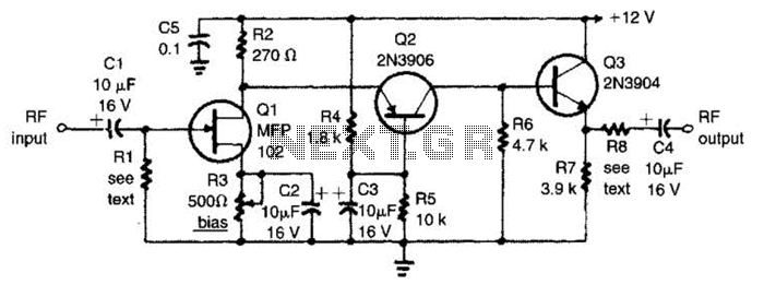
The circuit features a frequency response that spans from 100 Hz to 3 MHz, with a gain of approximately 30 dB. Field-effect transistor Q1 is arranged in a common-source self-biased configuration, and an optional resistor R1 is available to...
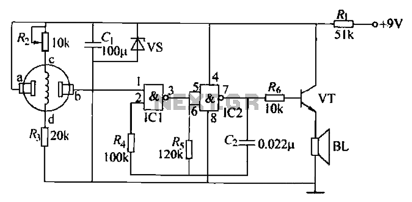
The combustible gas alarm circuit is depicted. The circuit comprises a gas sensor, a multivibrator, and audio output components. The multivibrator is implemented using two NAND gates within an integrated circuit (IC2) and includes external resistive and capacitive components....
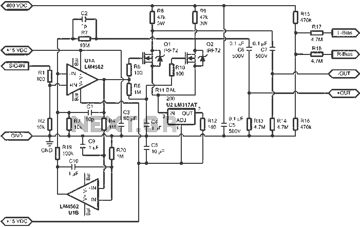
When connected to popular Stax Class 1 electrostatic headphones, the design illustrated in the figures may operate across the full audio bandwidth with a transmission voltage close to 200 Vp-p. Although the resistor divider can be modified to provide...

This design outlines a phone bug circuit. The wireless telephone line spy circuit is capable of transmitting phone conversations to a nearby FM radio. The circuit must be connected to a standard phone line. In the circuit, the first...
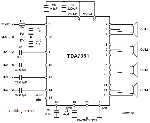
The amplifier is a quad amplifier circuit (amplifier with four inputs and four outputs) based on the TDA7381. This amplifier is designed for car audio systems, but it can also be utilized for other applications. The circuit has a...