
Stereo audio power amplifier circuit using TDA2822

The TDA2822 audio power amplifier circuit is designed to provide high-quality audio amplification in stereo applications. The TDA2822M integrated circuit serves as the core component, capable of delivering up to 2 x 1.5W of output power into an 8-ohm load, making it suitable for small audio devices, radios, and portable speakers. The circuit typically operates on a supply voltage range of 4.5V to 15V, allowing for flexibility in various power supply configurations.
In the schematic, the TDA2822M is connected to various passive components that facilitate its operation. Input capacitors are used to block DC offsets and allow only the AC audio signals to pass through. Feedback resistors may be included to set the gain of the amplifier, ensuring that the output signal is appropriately amplified without distortion.
The circuit may also include bypass capacitors near the power supply pins of the TDA2822M to filter out noise and stabilize the voltage supply. Output coupling capacitors are typically employed to prevent DC from reaching the speakers, ensuring that only the amplified audio signal is delivered.
For enhanced performance, alternative ICs such as KA2209 and NJM2073 can be considered. The KA2209 offers similar characteristics and can be used in applications where additional features or specifications are required. The NJM2073, on the other hand, provides a different output configuration and may be suitable for specific audio applications requiring distinct design considerations.
Overall, the TDA2822 audio power amplifier circuit is a versatile and efficient solution for audio amplification in various electronic projects, providing reliable performance and sound quality.Circuit stereo TDA2822 audio power amplifier circuit schematics Circuit Electronics, In this series I use IC tda2822M as the main amplifier, but if you want to use in addition to IC TDA2822M you can use ic I mentioned this is KA2209, NJM2073.. 🔗 External reference
Related Circuits
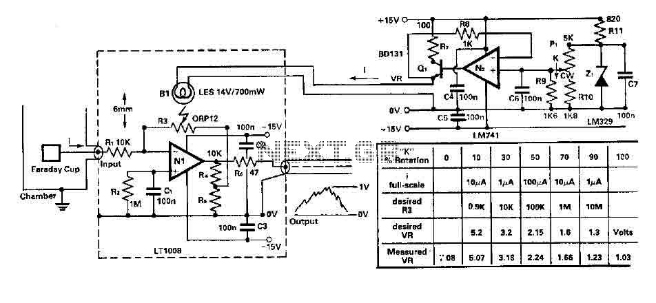
To amplify small current signals as an electron collector inside a vacuum chamber, it is advantageous for reasons related to noise and bandwidth to have a "head-amplifier" connected to the chamber. Operational amplifier 1 is a precision device featuring...
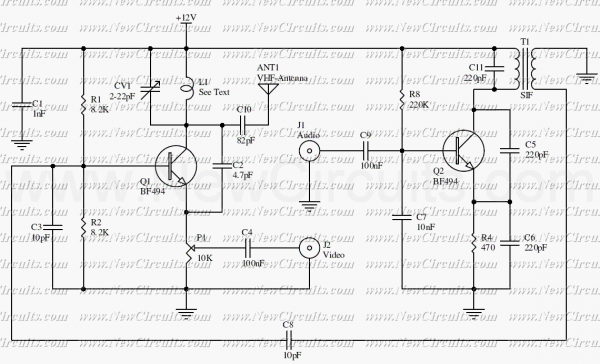
The circuit presented here is a simple audio/video transmitter with a range of 3 to 5 metres. The A/V signal source for the circuit may be a VCR, a satellite receiver or a video game etc. A mixer which...
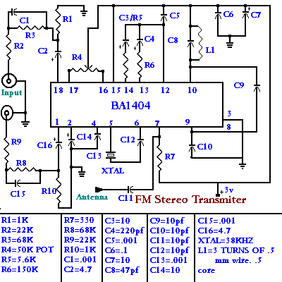
This project is straightforward to construct and will transmit high-quality sound within the FM band (88-108 MHz). An important component is that the... This project involves the design and construction of a simple FM transmitter capable of broadcasting audio signals...
This diagram originates from the Progressive Communications Receiver featured in most recent ARRL Handbooks. The amplifier is utilized wherever an intermediate frequency (IF) amplifier is necessary. W6BKY has published an article on Hamradio-online that details the construction of this...
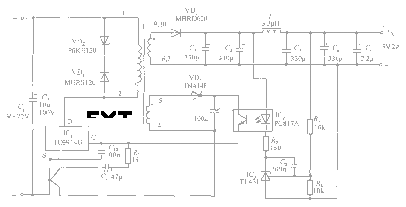
The circuit diagram includes an input filter capacitor C1 and a primary clamp composed of VDz and VD1. The resistor R1 is connected to the control terminal. C2 serves as a bypass capacitor. The TOP414GC-S is connected in parallel...
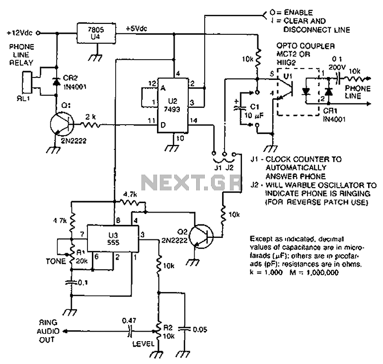
Check the loop circuit for an automatic telephone answering system or a tone generator for use in reverse automatic repair. The loop circuit in an automatic telephone answering system is designed to detect incoming calls and activate the answering mechanism....