
Battery charger and PSU

The circuit designed for charging and powering digital cameras incorporates two main components: a charger and an adapter. The adapter utilizes a transformer to step down the mains voltage, which is then rectified by a bridge rectifier to convert the AC to DC. A buffer capacitor smooths out the rectified voltage to provide a stable DC output. The adjustable voltage regulator LM317 is employed to provide a variable output voltage suitable for the camera, adjustable within the range of 2 to 9 volts, depending on the specific requirements of the camera model being used.
In the charger section, a 7805 fixed voltage regulator functions as a current generator, ensuring a constant current flow during the battery charging process. The charging current can be finely tuned using a 100-ohm, 1-watt potentiometer, allowing for adjustments between 50 mA and 300 mA. This is crucial for accommodating different battery types and their specific charging requirements. A small current measuring instrument is included in the circuit to provide real-time feedback on the charging current, enhancing usability.
The design allows for the simultaneous charging of one to four NiMH batteries. A switch is incorporated to select the number of batteries being charged, which is essential to ensure the charging current is appropriately adjusted in accordance with the specifications provided by the battery manufacturer. Notably, the circuit does not include a mechanism for monitoring the charging time or the condition of the batteries. Instead, the manufacturer-recommended charging time, typically ranging from 14 to 16 hours, is adhered to. To address the lack of a built-in timer, a mechanical mains timer is integrated into the system, allowing for automated control of the charging duration while remaining cost-effective and straightforward in design. This approach provides a practical solution for users needing to charge batteries for digital cameras efficiently.This circuit was created for digital cameras. It's known the digital cameras have considerable power consumption. For example my camera Minolta E223 requires approximately 800 mA. In practice a mains power supply or high capacity NiMH accumulators (batteries) can satisfy this demand. This circuit consists of two parts, charger and adapter. The transformer, rectifier bridge and buffer condensator are common. Adapter is quite simply its main part is an adjustable voltage regulator LM 317 according to usual setting.
Output is a suitable for camera jack plug. Voltage can be adjusted in range 2-9 V. In the charger circuit a 7805 fixed voltage regulator works as current generator assured constant current during charging. This charging current can be adjusted with the 100 /1W potentiometer in range about 50-300 mA indicated by a small current measuring instrument.
From one to four batteries can be charged simultaneously. The switch must be set according to number of batteries, and charging current of batteries given by manufacturer must be adjusted. This circuit doesn't measure charging time and charging condition of batteries. Manufacturers give charging time, usually 14-16 h. I solved this problem with a simply, cheap mechanical mains timer. I think its accuracy is sufficient. 🔗 External reference
Related Circuits
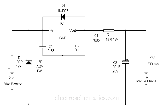
This circuit provides a simple and efficient method to draw current from a motorcycle battery to charge a mobile phone. Most mobile phone battery packs consist of three 1.2-volt cells, resulting in a total voltage of 3.6 volts. For...
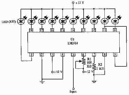
this circuit uses the LM3914 and should be powered by its own battery, otherwise you might get an inaccurate reading. hook the to-be-monitored battery to pin 5 of the chip. More: all resistors are 5 or 10 percent tolerance,...
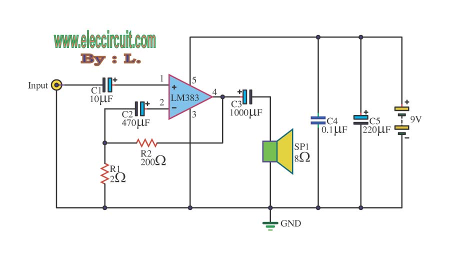
The circuit operates with a 9-volt power supply using the LM386 amplifier IC, which has a power output range of 300-800 mW, depending on the supply voltage, which can vary from 4 to 15 volts. The input signal is...
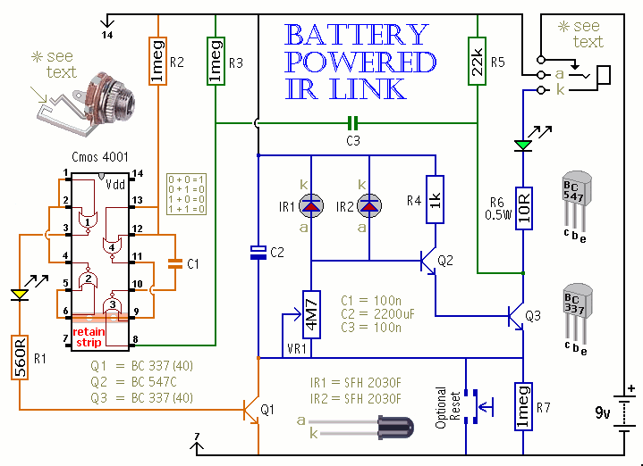
This is a battery-powered infrared (IR) link that can be utilized in multiple rooms. The standby current is exceptionally low, resulting in excellent battery life. The circuit is designed to shut down when faced with extraneous IR radiation, effectively...
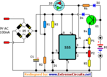
This automatic NiCd charger for 9V NiCd batteries utilizes the properties of a 555 timer and is straightforward to construct. The design allows for continuous charging of the battery without the risk of overcharging or discharging. With the specified...
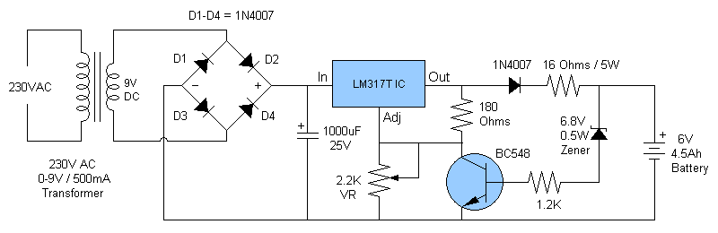
This article discusses a fully automatic 6V 4.5AH battery charger circuit that utilizes the LM317T integrated circuit along with a few additional components. The circuit is designed to charge a 6V lead-acid battery. The circuit utilizes the LM317T voltage regulator,...