
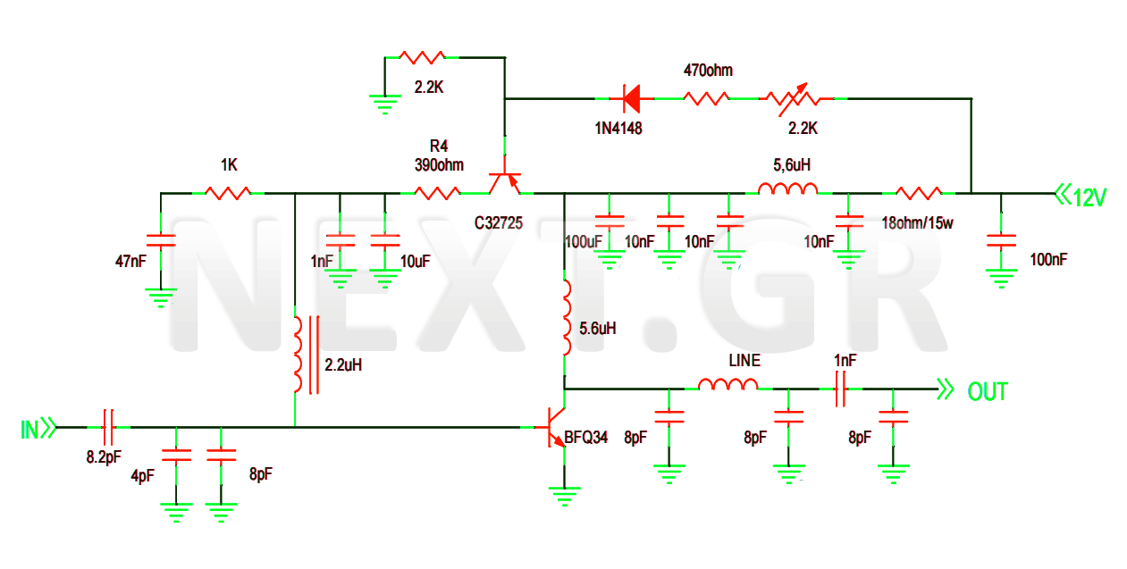
amplifier audio small to use with 9v battery operated
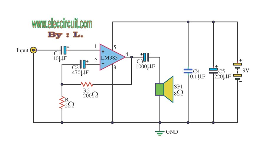
The LM386 amplifier circuit is designed for straightforward implementation in audio applications, particularly where space and component count are critical. The circuit's architecture facilitates a robust audio amplification solution with built-in noise reduction and frequency response enhancement features. The use of capacitors for coupling and filtering ensures that only the desired audio frequencies are amplified, while DC components are effectively blocked. The variable resistor VR1 allows for user-friendly control of the output level, making this circuit adaptable for various audio sources.
The configuration of the LM386 in this circuit supports a variety of audio projects, from simple amplifiers to more complex audio processing systems. The feedback loop created by R2 and C3 is crucial for maintaining audio fidelity, particularly at higher frequencies, which is often a challenge in audio amplification. Additionally, the circuit's low power consumption makes it suitable for battery-operated devices, enhancing its versatility in portable applications.
The overall design is conducive to educational purposes, allowing students and hobbyists to explore audio amplification principles without the complexity of more advanced circuits. The LM386's established reputation in the electronics community further underscores the reliability and effectiveness of this circuit for both learning and practical applications in audio engineering.When entering the power supply 9-volt circuit IC1 number LM386 amplifier IC size is 300-800 mW, Depending on the power supply circuit with, This is from 4-15 volts. Once entered into the input pin 3, The non inverting pin to amplifier non-return phase. C1 will be served cut out the noise input to ground. And C2 increases the rate of amplifier, C2 is to add more value. But if the C2 Too much distortion (the C2 should not exceed 100uF). The output of IC1 is out of the pin 5 through C4 coupling audio signals to better and DC block and not passed to the speaker. For the audio portion will also be fed back through R2 and C3 to the high frequency response better. This circuit number LM386 IC is used as the IC, which is popular is that it has. It is a simple circuit. Less equipment items. Suitable for use or used in small trials. The properties of the IC can be used from 4V-12V power supply for low current at 50 mA only. And the frequency response from 40Hz 100 kHz rate of expansion of 46 dB and distortion. When entering the power supply light LED1 circuit to tell the operating environment of the circuit. C6 and C7, with a page filter to smooth then be entered through one input sound signal. C1 coupling signal protection dc voltage noise in circuit to the sound signal that is transmitted through VR1 for controller level reputation of sound signal and then sent to the input to pin 3 of IC1.
boost up output at pin 5 through C5 for protection dc voltage and meet the low frequency better and send out put speakers. The C4 and R1 is acting eliminate noise signal out and the pin 1 of IC will have a jumper for. to access the C3 to boost up rate increase in case the circuit to be used to boost up signal is very small.
🔗 External reference
Related Circuits
This circuit design features a modular arrangement that enables users to select only the modules best suited to their needs, allowing for the construction of a chain ranging from one to five modules in length. For those seeking a...
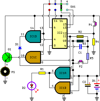
Pressing P1 resets IC2, which then begins oscillating at a frequency determined by R3 and C1. With the specified values, this frequency is approximately 4Hz. LED D2, controlled by IC1A and IC1B, flashes at the same oscillator frequency, indicating...
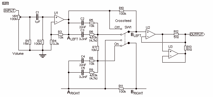
SW1 bypasses the crossfeed network. I have reconfigured the original crossfeed schematic so that now the 100k resistor always bridges the bypass switch and thereby reduces any 'crackle' or 'click' or whatever you may call them. Don't omit these...
This project involves the construction of a VHF-UHF linear amplifier capable of operating at frequencies ranging from 47 MHz to 740 MHz. It serves as the final output stage for any transmitter functioning within these frequencies. The amplifier utilizes...
The original radio circuitry has been transformed into a block diagram representation. The electrical schematic is illustrated in Figure 1-27, which depicts a typical single-tube amplifier of Group A. One figure represents the audio amplifier circuit for the original...
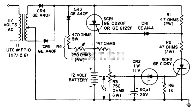
The circuit is designed to charge a 12-volt component selection at a maximum current of six amperes. Once the battery voltage reaches its fully charged level, the SCR shuts off, and a trickle charge, determined by the resistance value...
Warning: include(partials/cookie-banner.php): Failed to open stream: Permission denied in /var/www/html/nextgr/view-circuit.php on line 713
Warning: include(): Failed opening 'partials/cookie-banner.php' for inclusion (include_path='.:/usr/share/php') in /var/www/html/nextgr/view-circuit.php on line 713