
Autotransformer decompression control circuit

The circuit described involves a sequential control mechanism for a motor startup using a combination of contactors and relays to ensure safe operation and smooth transition from a reduced voltage startup to full voltage operation.
The power switch serves as the primary means of controlling the entire system. Once the power is on, the operator can initiate the motor start process by pressing the start button SB2. This action energizes the KM1 contactor, which closes its main contacts, allowing current to flow through the autotransformer TM. The autotransformer provides a reduced voltage to the motor, facilitating a soft start that minimizes inrush current and mechanical stress on the motor.
As KM1 engages, it also activates its auxiliary contacts, which play a crucial role in the self-locking mechanism. This ensures that KM1 remains energized even after the start button is released. The auxiliary contacts of KM1 are also responsible for energizing the intermediate relay KA1, which further enhances the control logic of the circuit.
The power-delay time relay KT is an essential component that introduces a timed delay to allow the motor to reach near its rated speed before transitioning to full voltage. Once the motor speed is adequate, the delay contact of KT closes, energizing KA2. This relay prepares the system for the next phase of operation.
KA2's function is critical as it allows for the transition from the soft start provided by KM1 to full power operation through KM2. The opening of KA2's break contact effectively disconnects the power from KM1, ensuring that the motor is no longer supplied with reduced voltage while simultaneously resetting the system for future operations.
Overall, this circuit design emphasizes safety and efficiency, utilizing multiple relays and contactors to control the motor's operation in a manner that prevents electrical faults and optimizes performance during startup and normal operation. Close the power switch os, press the start button SB2. KM1 contactor is energized combined self-locking, the main contacts are closed, the autotransformer TM connected between the power source and the motor, the motor start decompression. KM1 move off the auxiliary contacts are open, can not guarantee KM2 was electric; KM1 of auxiliary units are moving together contacts, the intermediate relay KA1 was electric suction combined self-locking. KA1 of moving together contact closure, making power-delay time relay KT is energized incl. When the motor speed when close to its rated speed, the delay of KT closed front contact is closed, the intermediate relay KA2 was electric heating combined self lock.
KA2 of moving together contact closure, in preparation for the KM2 was electric. KA2 the break contact open, the United States die of hunger transcript millet M1 tank costs of electricity release j KM1 main contact is disconnected, cut off the power to the motor, KM1 moving off contact closed reset, so that JI j KM2 self-locking motor departing from the transformer coupled by Jun KM2 main contact normal operation full pressure.
Related Circuits
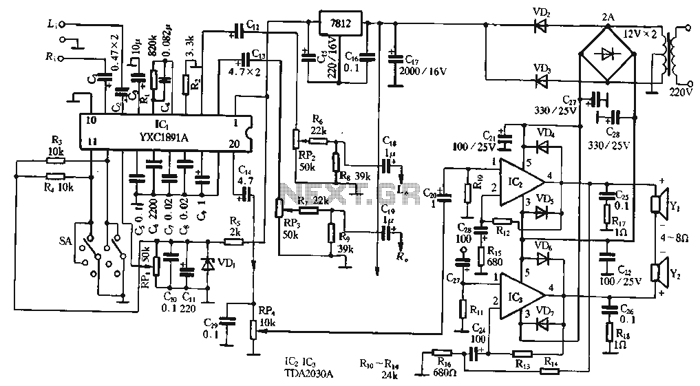
The ptPC1891A application circuit features a working state switch (SA) with a total of four options. It primarily utilizes ICs 11 and 12 to set different logical levels, as referenced in Table 5-12. The high level is denoted as...
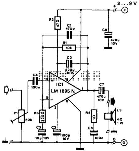
This amplifier operates with supply voltages ranging from 3 V to 9 V and can deliver an output power ranging from 100 mW to 1 W into a 4-ohm load. The bandwidth is approximately 20 kHz at a 3...
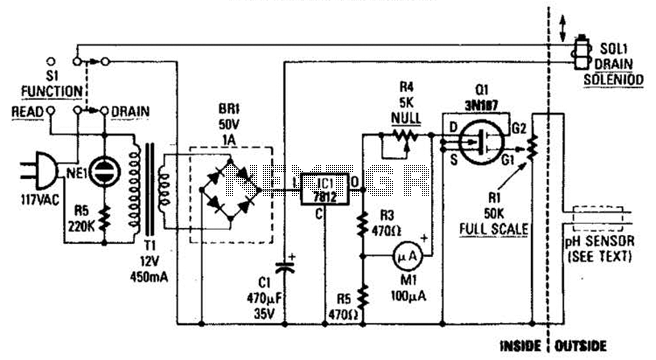
The drain-to-source resistance of Q1 varies depending on the acidity of the sample presented to Q1's gate circuit. This variable resistance influences the current flowing through the bridge, which is proportional to pH. The circuit involves a field-effect transistor (FET),...

An NPN bipolar transistor is typically utilized for relay switching, particularly with 12V coil-rated relays, as it helps maintain circuit separation. A diode is also added to prevent issues. The necessity of driving the relay with a transistor depends...
The project originated from a request by Tony Bowler, a member of the Long Eaton Club, who sought assistance in converting a "Golden Oldie" model to electric free-flight. He selected Vic Smeed's "Debutante" to be powered by seven AE...
The pyroelectric infrared sensor head operates as illustrated in the accompanying figure. Upon detecting an infrared signal from a human body within its monitoring zone, the sensor head generates a positive pulse signal. This signal is transmitted to the...