
Battery charger using LM317 regulator circuit

The described battery charger circuit utilizes a minimalistic design, leveraging the LM317 voltage regulator, which is known for its versatility in providing a stable output voltage. In this configuration, SCR1 acts as a switch that remains off until the circuit is powered, ensuring that no current flows to ground initially. This feature is critical for maintaining circuit integrity during startup.
Diode D1 plays a crucial role in protecting the battery by blocking reverse current flow when the power supply is disconnected. This prevents potential damage to the battery and ensures longevity by avoiding unnecessary discharge through the LED and SCR components. The inclusion of limiting resistor R1 is essential for controlling the current flowing to the battery, thereby preventing overcharging, which can lead to battery failure.
The bias resistor R2 aids in setting the appropriate reference voltage for the LM317, allowing it to regulate the output effectively based on the battery's charge state. The operation of the circuit is indicated by LED1, which provides visual feedback on the charging status. When LED1 is on, it indicates that the battery is being charged in voltage-regulating mode, which is suitable for maintaining the battery at a specific voltage level. In contrast, when LED1 is off, the circuit switches to current-regulating mode, which is necessary for the final stages of charging, ensuring that the battery receives a safe and controlled current.
Overall, this battery charger circuit exemplifies an efficient design that balances simplicity with functionality, making it suitable for various battery charging applications.As you can see in this schematic circuit this battery charger has extreme few components, but is doing a very good job. When power is applied to the circuit the SCR1 is off, so there is no bias-current path to ground. The LM317 is connected to the battery through diode D1, limiting resistor R1, and bias resistor R2. The D1 diode is used to preve nt the battery from discharging through the LED and the SCR when power is removed from the circuit. When LED1 is on, the circuit is in the voltage-regulating mode and when LED1 is off, the circuit is in the current-regulating mode. 🔗 External reference
Related Circuits
The construction is nearly complete, and a circuit diagram has been created. The design has been finalized and documented on paper. The circuit diagram represents a critical stage in the development of an electronic project, serving as a blueprint for...
It is essential to consider migrating to PIC microcontrollers and exploring compilers such as those offered by Proton Smart, which include Sony IR and Philips RC5 codecs. This approach is particularly advisable for security-sensitive applications. Additionally, Bluetooth and Wi-Fi...
An LED, or Light Emitting Diode, is a semiconductor device that allows current to flow in one direction while blocking it in the opposite direction. This characteristic makes LEDs polarized components, having a positive side known as the anode...
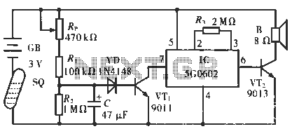
The circuit operates in such a way that when the patient is typically in an upright position, the SQ mercury switch is turned off, resulting in the alarm circuit being inactive. When the patient lies down, the SQ switch...
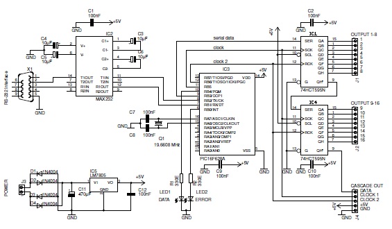
This basic PIC-based RS-232 serial interface can control up to 120 digital TTL outputs. The described circuit utilizes a PIC microcontroller to facilitate communication via the RS-232 protocol, which is a standard for serial communication. The interface primarily serves to...
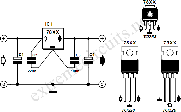
The voltage regulators from the 78xx series are commonly used in many analog power supplies. While it may seem unnecessary to elaborate on them due to their prevalence, it is beneficial to emphasize their key aspects. The 78xx series...