
Professional Mobile (1G 2G 3G 4G) & WiFi Jammer Circuit
Mobile telephony commenced with the first generation, known as 1G. It was a wireless analog system that supported data transfer speeds of up to 2.4 kbps in the 1980s. The second generation, 2G, emerged in the late 1980s and evolved throughout the 1990s, utilizing digital signals for voice transmission with a channel speed of 64 kbps. This advancement allowed for encrypted dialogues, greater security, and higher transmission rates for non-voice services such as SMS and email, while emitting less power and radiation.
The third generation, 3G, began in the late 1990s and progressed throughout the 2000s, with supported speeds ranging from 128 kbps to 2 Mbps. Key features of 3G technology include video calls, internet connectivity with speeds up to 384 kbps, high data transfer rates for multimedia applications, video streaming capabilities, and enhanced positioning services through GPS technology.
4G technology, as the successor to 2G and 3G, offers broadband speeds similar to Wi-Fi but over significantly longer distances than the 100-meter range of typical Wi-Fi. It supports much higher upload and download speeds, as detailed in various tables.
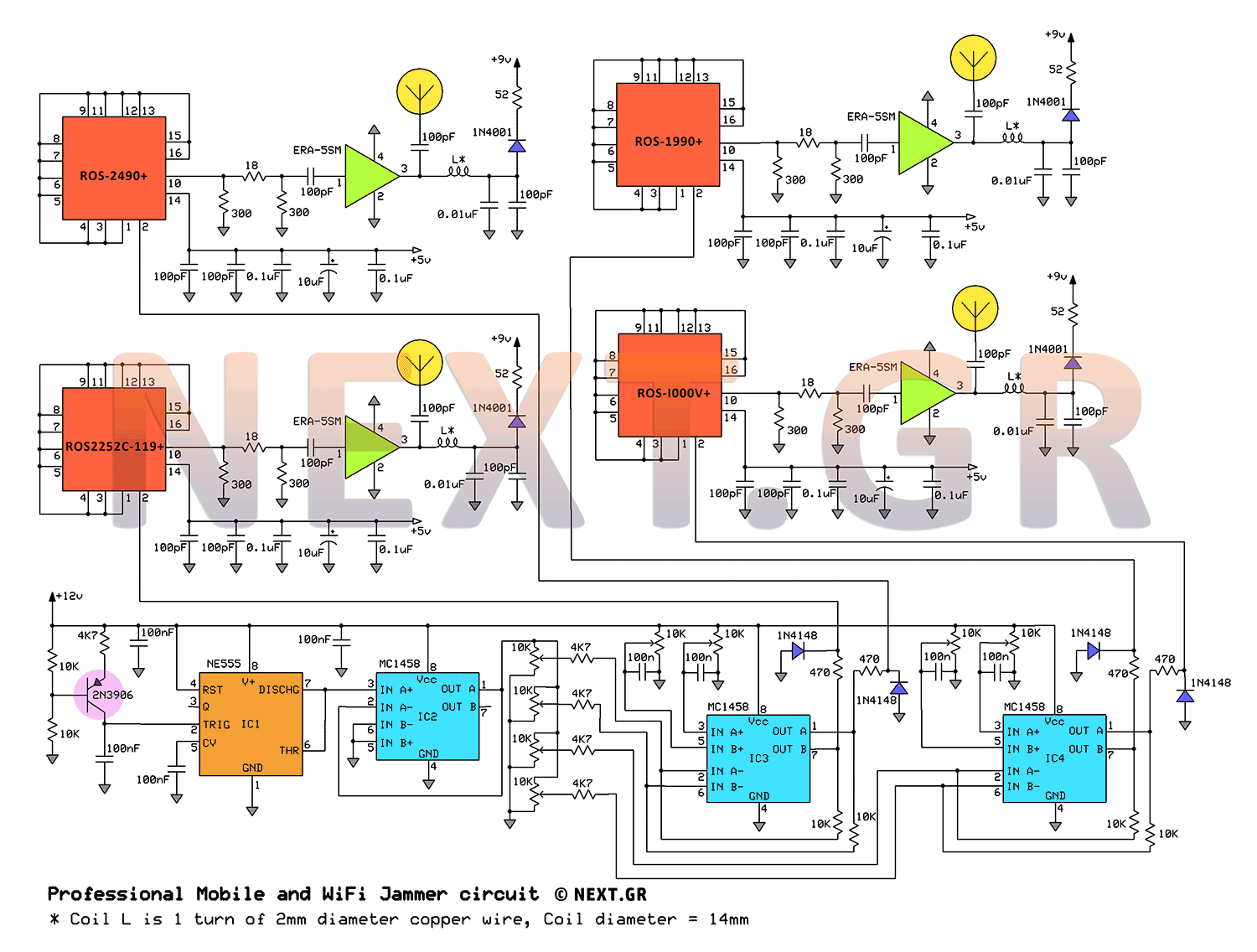
The circuit focuses on local noise interference within lower spectral bands, disrupting wireless communication between mobile phones and their respective base stations. Interference with uplink frequencies affects the transmission from the mobile phone to the base station antenna, potentially blocking the provider's network coverage.
The Voltage Controlled Oscillator (V.C.O.) plays a crucial role in this circuit. The adder circuit merges sawtooth voltage with noise, directing the final signal to the V.C.O. The design includes four V.C.O.s, each driven by the aforementioned adder, with their outputs amplified by ERA-5SM+ amplifiers. Initial adjustments to the V.C.O. are made to center on the desired frequency band. Following this, the appropriate sawtooth voltage signal is added to cover the bandwidth and generate the necessary interference.
The frequency range subjected to interference spans from 930 MHz to 955 MHz (2G), adequately covering the lower band frequency range of 2G from 925 MHz to 960 MHz. While separate frequency adjustments for each V.C.O. are not feasible due to a single output feeding all units, a new board has been developed to provide distinct silent voltage signals for each V.C.O.
An integrated NE555 timer is utilized alongside a 100 nF capacitor and a 12-volt supply to ensure a minimum voltage of 9 volts. This configuration allows the NE555 to generate the sawtooth voltage, subsequently driving a voltage isolator (Buffer MC1458) to maintain signal integrity.
The circuit includes four potentiometers, each accepting the sawtooth voltage and directing it to the corresponding mixer through a 4.7k ohm resistor combined with noise. Each potentiometer (P6 to P9) independently adjusts the offset for its respective V.C.O., ensuring the DC voltage component aligns with the appropriate V-tune points. The mixer integrates the sawtooth voltage with the final signal directed to the corresponding oscillator, protected by 1N4148 diodes to prevent negative voltage from passing.
Optimization of the circuit can be achieved through testing in various environments, as well as by utilizing more suitable antennas to enhance its operational range.This Jammer circuit can be used indoor or outdoor and the coverage/range that offers is about 30 meters in order to disconnect the wireless devices from their communication with the base station. In the circuit design, we use the frequency ranges reserved by mobile operators as well as the 2.4-2.5Ghz band that does not require Wi-Fi authorization.
Let's look at the frequency ranges used by the four different generations of mobile phone systems.
Mobile telephony started with the first generation known as 1G. It was a wireless, analogue system that supported data transfer speeds of up to 2.4 kbps back in the 1980s.
The second generation of 2G began in the late 1980s and developed throughout the 1990s. The voice transmission was done with a digital signal. Supported speed per channel was 64 kbps. It was advantageous in relation to the first generation in the fact that the dialogs could be encrypted before transmission (greater security) and higher transmission rate (frequency range) was supported by other non-voice services such as SMS and e-mail.
It required less emitted power and therefore caused less radiation.
The third generation of 3G began in the late 1990s and developed throughout the 2000s. Supported speeds ranged from 128 kbps up to 2 Mbps. Some of the advantages introduced by third-generation technology are:
- • Video calls are no doubt one of the most talked about 3G services.
Plus, in addition to listening to one's conversation, he will be able to see him live on his mobile screen. Of course, both compatible devices should be available. - • Connecting to Intemet in addition to direct and seamless, now delivers speeds of up to 384kbps.
- • High data transfer speeds make it much easier to use different multimedia applications.
For example, sending a MMS to another subscriber does not take more than 10 seconds - when in 2G networks this time exceeds 1 minute. - • Video streaming is another of the services provided by 3G networks. The high transmission rate allows real-time, moving and high-resolution audio communication. Thus, it is possible to watch television programs, live or recorded, regardless of place and time.
- • Positioning services, combined with GPS technology, which combine maps of the area we find, find the best route to our destination, various neighboring points of interest, etc.
4G technology as its name implies is the successor generation of 2G and 3G.
In the 2G generation we moved from analog to digital transmission where we could send messages or have e-mail on our mobile and then we went to 3G (3G) where we could have access to the internet on the mobile or on the computer And download live music files at speeds of up to 1.4 Mbps.
With 4G technology, broadband similar to Wi-Fi is achieved, but over much longer than the 100-meter Wi-Fi. Also supported speeds for uploading or downloading files become much larger, as shown in the tables below.
|
Standard |
Download |
Upload |
|
|
2.5G |
GPRS |
114 Kbps |
20 Kbps |
|
2.75G |
EDGE |
384 Kbps |
60 Kbps |
|
3G |
UMTD |
384 Kbps |
64 Kbps |
|
W-CDMA |
2 Mbps |
153 Kbps |
|
|
HSPA 3.6 |
3.6 Mbps |
348 Kbps |
|
|
HSPA 7.2 |
7.2 Mbps |
2 Mbps |
|
|
Pre-4G |
HSPA 14 |
14 Mbps |
5.7 Mbps |
|
HSPA + |
56 Mbps |
22 Mbps |
|
|
WiMAX |
6 Mbps |
1Mbps |
|
|
LTE |
100 Mbps |
50 Mbps |
|
|
4G |
WiMAX 2 |
1Gbps |
500 Mbps |
|
LTE Advanced |
1Gbps |
500 Mbps |
|
Standards |
Technology |
Voice Switching |
Data Switching |
Data Rates |
|
|
lG |
AMPS,TACS |
Analog |
Cίrcuit |
Circuit |
Ν/Α |
|
2G |
GSM ,CDMA,EDG E,GPRS |
Digital |
Cίrcuit |
Cίrcuit |
236.8 kbps |
|
3G |
YTMS, CDMA2000, HSPDA,EVDO |
Digital |
Cίrcuit |
Packet |
384 kbps |
|
4G |
LTE Advanced, IEEE 802.16 (WiMax) |
Digital |
Packet |
Packet |
Up to 1Gbps |
|
2G |
3G |
4G | Wi-Fi | ||||
| Up link | Down link | Up link | Down link | Up link |
Down link |
2400 - 2500 | |
|
Others |
880-890 |
925-935 |
1950 -1965 |
2140 -2155 |
1750 -1785 |
1845 -1880 |
|
|
Wind |
890-900 |
935-945 |
1.940 -1950 |
2130 -2140 |
1710 -1725 |
1805 - 1820 |
|
|
Vodafone |
900-915 |
945-960 |
1920 -1940 |
2110 -2130 |
1725-1750 |
1820 -1845 |
|
We are dealing exclusively with the local noise interference in the lower band (Spectral Bands), the wireless communication of the mobile telephone station with the mobile phone. This has the effect of interrupting the communication of the mobile phone with the base station at a small geographical distance around the mobile.
Up-Link frequencies are used to transmit the mobile phone to the base station antenna of the mobile phone company.
If we interfere with this frequency range, we would interfere with the reception of the wireless base station rather than with the reception of the mobile phone, possibly blocking the coverage of the provider's network with any consequences.
The Voltage Controlled Oscillator (V.C.O.)
The adder circuit combines the sawtooth voltage with the noise to lead the final signal to the voltage-controlled oscillator V.C.O. In this way, we manage to make the noise over the sawmill. The circuit consists of four V.C.O. (ROS-I000V+, ROS-1990+, ROS2252C-119+, ROS-2490+) whose input is driven by the adder mentioned above, and their output is enhanced by the ERA-5SM+ amplifiers.
We must first adjust the V.C.O.
In the center of the frequency band that we want to insert. Once we have set the center frequency, we add the appropriate sawing voltage signal to cover the bandwidth of the particular frequency band and the noise of the appropriate power that causes the interference. VCOs work in the 2G, 3G, 4G, and Wi-Fi frequency ranges.
In the spectrometer we will see the interference we create in the frequency range from 930MHz to 955MHz (2G) while the lower band frequency band of the 2G band is from 925MHz to 960MHz.
The interference we generate sufficiently covers the desired frequency range. As long as the frequency bands that we intend to interfere with, we have taken further spectral images for the other three bands (3G, 4G and Wi-Fi).
As shown in the circuit, we can not separately adjust the frequency ranges for each VCO, because only one output is used that simultaneously feeds all four VCOs. In order to solve this problem, we have built a new board with four different silent voltage signals, one for the supply of each VCO.
The integrated NE555 has been used in conjunction with the C3 (100nF) capacitor and a 12 Volt supply that ensures the minimum required voltage of 9 volts on the foot 2.
As a result, the pin 6 of the NE555 creates the sawing voltage and then drives a voltage isolator (Buffer MC1458) so that its characteristics (width, frequency) are not affected by the input impedance of the next step.
In the circuit you can see the 4 potentiometers in the series that accept the sawing voltage and drive it to the corresponding mixer through the 4.7k resistance combined with the noise. Each potentiometer (P6 to P9) separately adjusts the offset of the corresponding VCO. With the VCO offset, we set the DC tension component so that it is between the appropriate V-tune points.
Then the mixer is mounted on the already formed sawing voltage, and the final signal is led to the input of the corresponding oscillator (VCO). The 1N4148 diodes are used at the input of the oscillators so that no negative voltage passes.
Optimization of construction can be achieved by testing it indoors and outdoors, different environments use as well as more suitable antennas will increace its active range.
Related Circuits
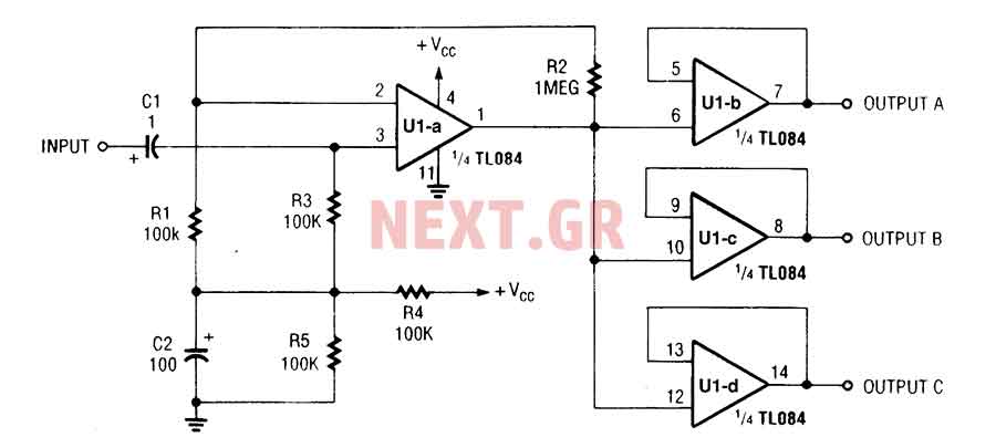
The three-channel amplifier output distribution uses a single TL084. The first step is to capacitive coupling with a 1.0 µF electrolytic capacitor. The entries are railways Vee Y2 or 4.5 V. This allows using a single 9 V power...
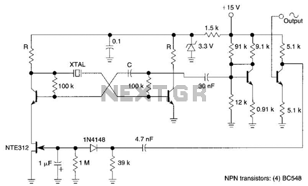
Q1, Q2, and the associated circuitry constitute a modified astable multivibrator where the loop gain is automatically adjusted to the threshold of oscillation by field effect transistor Q3. Q4 amplifies the signal at the collector of Q2 and isolates...
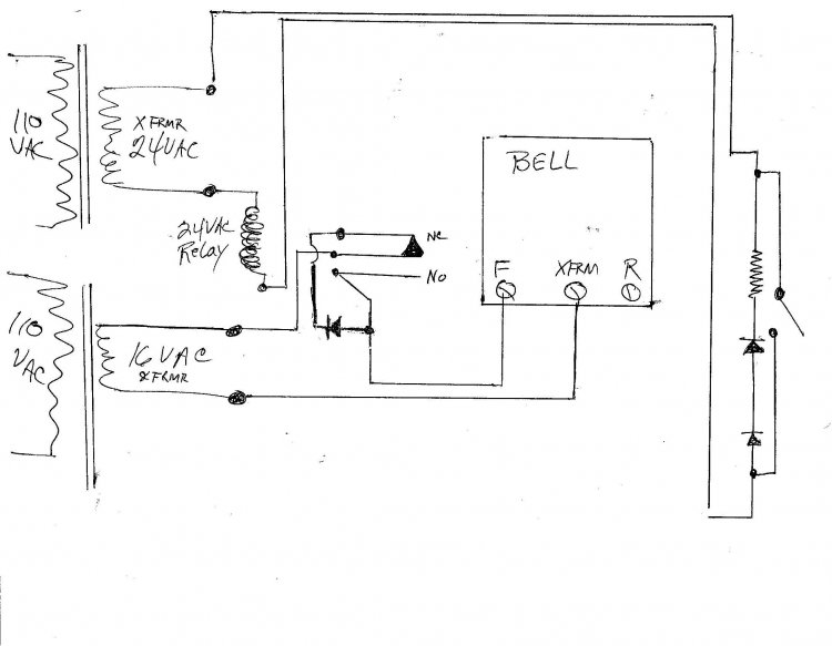
A new wired doorbell has been installed, specifically the Heath/Zenith Model #LE-65-B (Electronic). A new 16 Volt transformer was also added, along with a lighted pushbutton and a diode. Initially, all components functioned correctly, including the lighted pushbutton. However,...
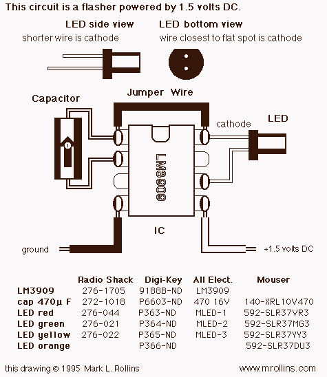
This project uses a 3909 IC and a few other parts; power is 1.5 volts DC. The project employs the 3909 integrated circuit (IC), which is a versatile component commonly used in various electronic applications, particularly in timer and oscillator...
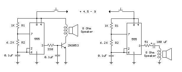
The following circuit is a basic 555 square wave oscillator. Features include a 1 kHz tone, simple circuitry, a current limit of 200 mA, reduced inductive voltage, and a supply voltage range of 4.5 to 9 volts. Components used...
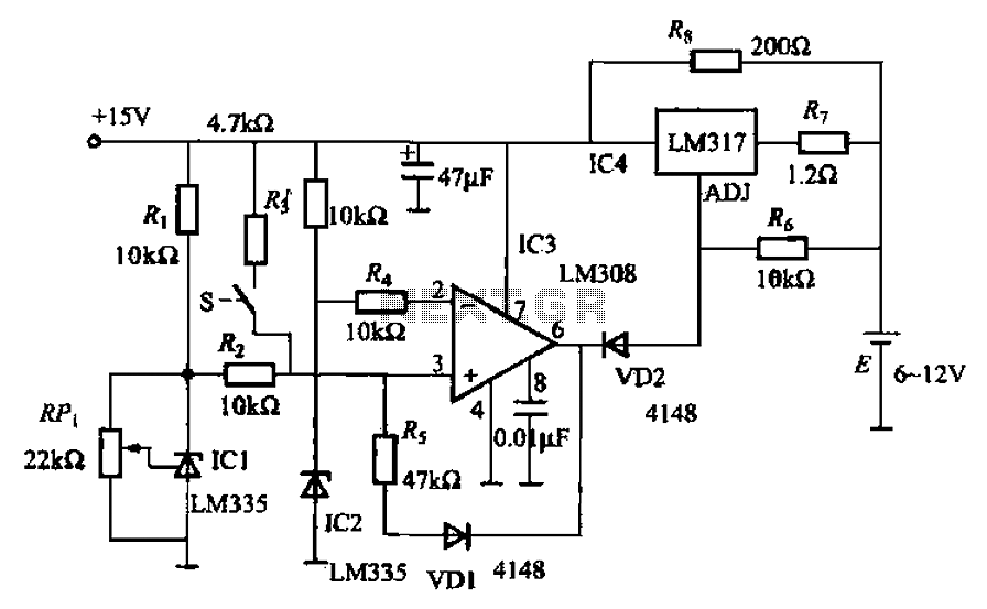
When fast charging a nickel-cadmium battery, the temperature control circuit, as illustrated in the accompanying figure, is designed to monitor the battery temperature to regulate the charging current. The circuit consists of Icl to IC3, which forms the temperature...
Warning: include(partials/cookie-banner.php): Failed to open stream: Permission denied in /var/www/html/nextgr/view-circuit.php on line 713
Warning: include(): Failed opening 'partials/cookie-banner.php' for inclusion (include_path='.:/usr/share/php') in /var/www/html/nextgr/view-circuit.php on line 713