
LA5522 Application Circuit
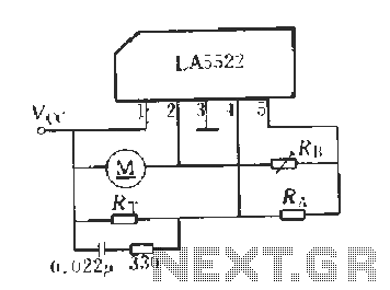
The LA5522 application circuit is designed for motor speed control, utilizing a feedback mechanism to stabilize the motor's operation under varying load conditions. The circuit is configured to monitor the supply voltage (Vcc), which is critical for the motor's performance. When external factors cause a fluctuation in Vcc, the circuit compensates by adjusting the motor speed accordingly.
The adjustable resistors (R1 and R4) serve as voltage dividers that sample the operational voltage across the motor. This sampled voltage is crucial as it reflects the actual performance of the motor in real-time. The error amplifier plays a pivotal role in this circuit by comparing the sampled voltage with a predetermined reference voltage (VREF). This comparison allows the error amplifier to identify any discrepancies between the desired motor speed and the actual speed.
The output of the error amplifier is linked to the bases of two transistors, which act as a control mechanism for adjusting the motor's power supply. By modulating the base current of these transistors, the output voltage at pin 3 is finely tuned to ensure that the motor operates at the desired speed.
The feedback control system is designed to maintain a negative relationship between the output voltage and the feedback signal. This characteristic is essential for achieving a closed-loop control system that can adapt to changes in load or supply voltage, thereby ensuring that the motor speed remains constant despite external variations.
In summary, the LA5522 application circuit effectively combines voltage sampling, error amplification, and transistor control to provide a reliable motor speed regulation system. This design is particularly useful in applications where precise speed control is necessary, ensuring optimal performance and efficiency of the motor under varying operational conditions.LA5522 Application Circuit It works briefly as follows: When the supply voltage vcc motor mechanical or negative change when the load changes, can cause changes in motor speed. And speed proportional to the anti-electric potential E. Marrow also change accordingly the voltage across the motor also changes. From adjustable resistor 1, 4 on two sampled voltage v ,. Reflects these voltage changes, delivered to the error amplifier inverting input terminal, compare it with the inverting input of the reference voltage VREF, the error amplifier controls the two rear base of the transistor, the output voltage (pin 3) is adjusted. 3-pin output voltage and V. . There was a negative relationship between the feedback control, the results tend to be closed-loop control to maintain a constant speed.
Related Circuits
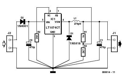
This 3-volt car adapter circuit is based on a standard LT1074CT switching regulator IC. The schematic shows the LT1074CT used as a positive step-down regulator. The 3-volt car adapter circuit employs the LT1074CT, which is a high-efficiency switching regulator capable...
A company has developed an intelligent temperature monitoring system using the ATMET 89C51 microcontroller. This system automatically records temperature data for a three-phase power supply, including high temperature and other relevant data, functioning as a black box. The ATMET...
A potentiometer regulates the firing point of the triac. Capacitor C4 is charged through resistors R3, R4, P1, and R5. After a specific duration, determined by the potentiometer setting, the charge in C4 becomes sufficient for the diac D...
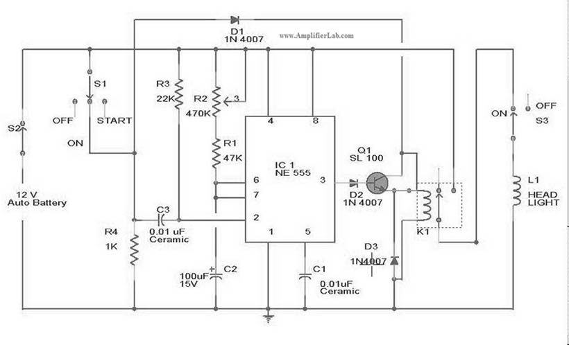
The circuit diagram for the automatic headlights turn-off circuit is presented here. This circuit can be installed in a car. The automatic headlights turn-off circuit is designed to enhance vehicle safety and convenience by ensuring that the headlights are automatically...
This AC drill speed controller circuit schematic allows for the control of the drilling speed of a borer or drilling machine. This project is based on the principle that... The AC drill speed controller circuit is designed to modulate the...
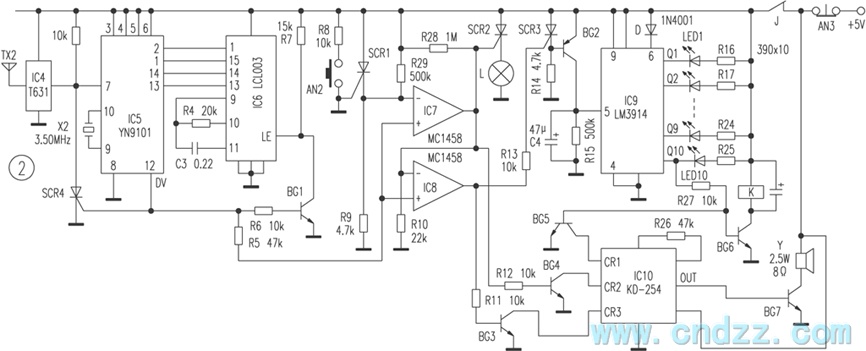
The wireless calling device consists of a calling unit and a host. These two components communicate using a DTMF encoder pulse. Each calling unit is assigned a unique code, although the circuits are identical. The calling unit is depicted...