
Battery ChargerCircuit Using IC 555
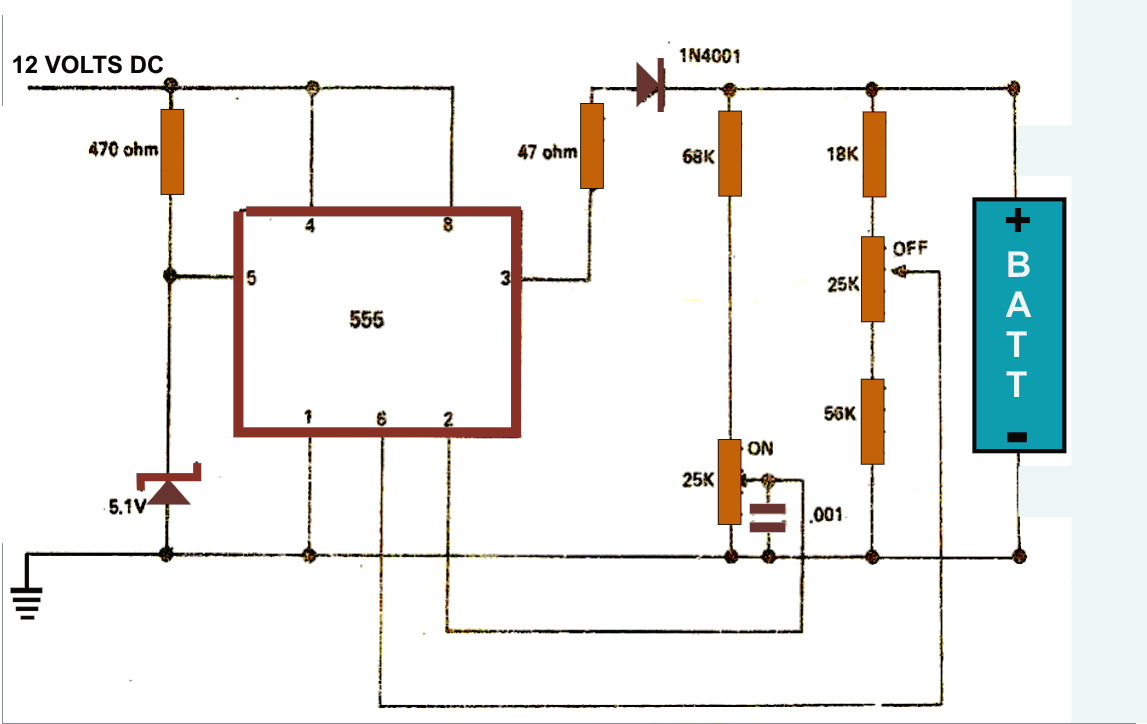
The battery charger circuit employs the 555 timer IC in astable mode to generate a PWM (Pulse Width Modulation) signal, which is crucial for controlling the charging process. The charging current can be adjusted by varying the resistor and capacitor values connected to the 555 timer, allowing for flexibility in charging different types of batteries, such as NiMH, Li-ion, or lead-acid.
The circuit typically includes a power supply input, which can range from a standard wall adapter to a solar panel, providing the necessary voltage and current for charging. The output of the 555 timer is connected to a transistor or a MOSFET, which acts as a switch to regulate the current flowing to the battery. A diode may also be included to prevent reverse current flow when the charging source is disconnected.
Additionally, the design may incorporate a voltage divider circuit for monitoring the battery voltage, ensuring that the charging process does not exceed the safe limits for the specific battery type. This can prevent overcharging, which could lead to battery damage or reduced lifespan.
For enhanced functionality, the circuit can include an LED indicator to signal the charging status, providing a visual cue that the battery is being charged. Overall, this simple yet effective battery charger circuit design is suitable for various applications, offering a practical solution for charging rechargeable batteries efficiently and safely.The simple battery charger circuit design shown here uses the versatile IC 555 as the main component. The circuit can be used for charging all types of rechargeable batteries within the specified limits as given in the article.
🔗 External reference
Related Circuits
The ZSSC1856 from ZMDI Company is a double-channel ADC integrated with an embedded MCU, composed of two chips packaged in a PQFN32 5x5mm format. The system's basic chip, the System Basis Chip (SBC), incorporates high voltage circuits, a LIN...
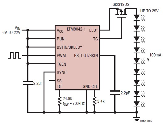
The LTM8042 integrates a boost power topology with a unique current loop to function as a constant-current source. The PWM input allows for LED dimming ratios of up to 3000:1, while analog dimming can be achieved with a single...
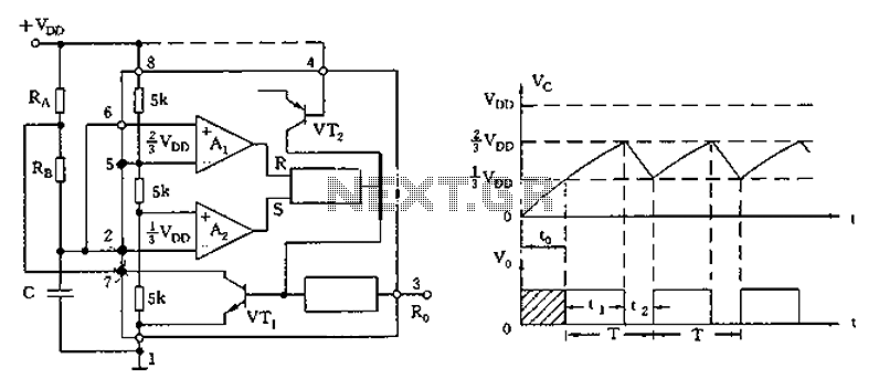
The circuit diagram illustrates the 555 timer (or 556 timer in half configuration) configured in astable multivibrator mode. It features three resistive and capacitive elements connected as shown. In one-shot mode, the trigger terminal (pin 2) is connected to...
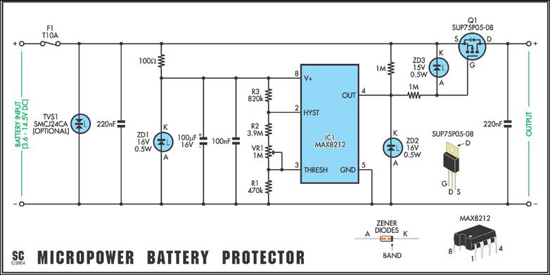
Protect expensive batteries from discharge damage with this mini-sized electronic cutout switch. It uses virtually no power and can be built to suit a wide range of battery voltages. The mini-sized electronic cutout switch serves as a crucial component in...
The modern mechanic switches are improved concerning old technology. We need, however, many times to replace some old switch or to check currents bigger than the durability of certain switches or simply we need something with a modern appearance....
In the 555 datasheet, there is a pulse width modulation circuit that resembles this one, with the only difference being that pin 5 is labeled as 'audio'. The 555 timer IC is a versatile device commonly used in various applications,...