
555 astable multivibrator circuit diagram
The 555 timer is a versatile integrated circuit commonly used in various applications, including timing, pulse generation, and oscillation. In astable mode, the 555 timer continuously switches between its high and low states, generating a square wave output. This mode is characterized by the absence of a stable state, making it ideal for applications such as clock pulses for digital circuits or LED flashing.
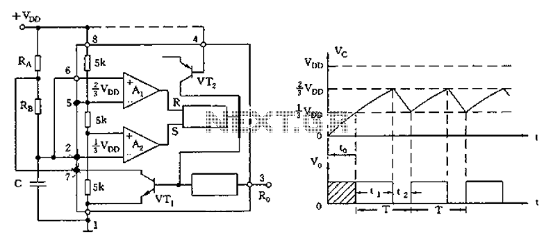
The configuration involves connecting two resistors (R1 and R2) and a capacitor (C) to the 555 timer. The resistors determine the charge and discharge times of the capacitor, which in turn sets the frequency and duty cycle of the output waveform. The output frequency (f) can be calculated using the formula:
\[ f = \frac{1.44}{(R1 + 2R2)C} \]
The duty cycle (D) is given by:
\[ D = \frac{R2}{R1 + 2R2} \]
In one-shot mode, the 555 timer generates a single pulse when triggered. In this case, the trigger input on pin 2 is connected to the charge and discharge circuit of capacitor C, allowing the capacitor to control the timing interval for the output pulse. The duration of the output pulse is determined by the resistor (R) connected to the discharge pin (pin 7) and the capacitor (C) connected to the threshold pin (pin 6). The pulse width (T) can be calculated as:
\[ T = 1.1 \times R \times C \]
This configuration allows for precise control over timing applications without the need for external triggering mechanisms, making it suitable for various electronic projects, including timers, pulse-width modulation, and frequency generation.As illustrated, the 555 (or 556 1/2) and three resistive, capacitive element connected as shown, constitute astable multivibrator mode. And one-shot mode except that only the t rigger terminal (pin 2) connected to the charge and discharge circuit C, rather than by external trigger control.
Related Circuits
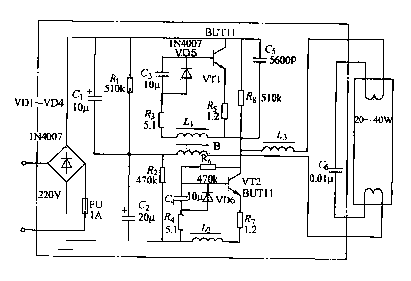
Electronic ballasts operate over a wide voltage range, provide fast startup with no noise or flicker, and contribute to energy savings. Their acceptance among users has been increasing. The circuit depicted in the figure represents a typical electronic ballast...
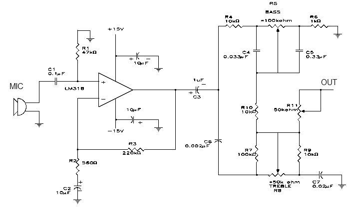
This simple microphone preamplifier is based on the LM318 operational amplifier. The LM318 operates as a standard non-inverting amplifier. Resistor R1 provides a ground input path for the bias current of the non-inverting input. The combination of R2 and...
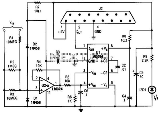
The adapter comprises a voltage-to-frequency converter integrated with a signal conditioning and protection circuit. J2 interfaces with the game port of a personal computer. Additional software references are available for use with this circuit. The voltage-to-frequency adapter functions by converting...
This circuit utilizes a single integrated circuit (IC) along with a minimal number of external components to display audio levels using ten LEDs. The input voltage can range from 12V to 20V, with a recommended operating voltage of 12V....
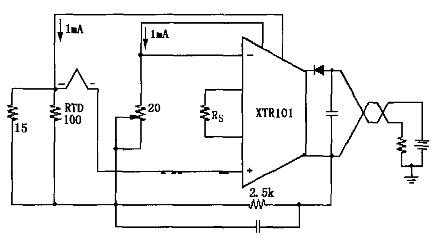
The circuit utilizes a type J RTD (Resistance Temperature Detector), where the resistance value is directly related to the temperature. Calibration of the zero point is facilitated by a 20-ohm adjustment potentiometer as specified by the manufacturer. The schematic features...
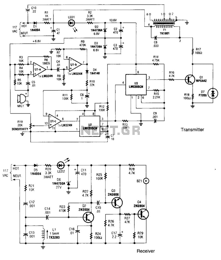
The transmitter operates by deriving its power directly from the AC line. The DC power required for the circuit is generated in two stages: the first stage powers the RF power amplifier, while the second stage supplies power to...
Warning: include(partials/cookie-banner.php): Failed to open stream: Permission denied in /var/www/html/nextgr/view-circuit.php on line 713
Warning: include(): Failed opening 'partials/cookie-banner.php' for inclusion (include_path='.:/usr/share/php') in /var/www/html/nextgr/view-circuit.php on line 713