
battery desulphation progress
The Lead-Acid Battery Zapper is a device designed to restore the capacity of lead-acid batteries through a process known as desulphation. During this process, sulfation—a common issue where lead sulfate crystals build up on the battery plates—can be reversed. The initial high peak voltage observed at the terminals serves as an indicator of the battery's state prior to treatment. As the desulphation progresses, the steady decline in peak voltage reflects the reduction of sulfation, ultimately leading to improved battery performance.
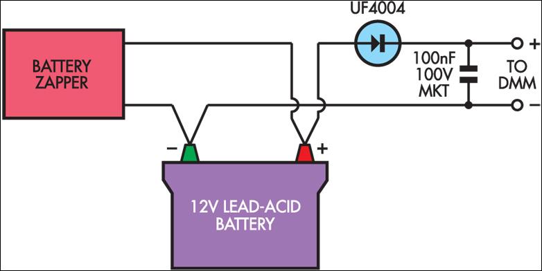
To construct a simple peak detector for monitoring the voltage, a fast recovery diode should be selected to ensure rapid response to voltage changes. The 100nF capacitor acts as a charge storage element, allowing the peak voltage to be captured and held for measurement. The high-impedance multimeter is crucial for accurately measuring the average DC voltage across the capacitor without significantly loading the circuit, which could skew the readings.
For practical implementation, the peak detector circuit can be connected in parallel with the battery terminals. The output from the capacitor can then be routed to the multimeter. Regular monitoring of the voltage across the capacitor will provide a clear indication of the progress of the desulphation process. As the treatment continues and the voltage approaches zero, the effectiveness of the desulphation process can be confirmed, indicating that the battery is likely to regain its capacity. This method provides a straightforward and effective means of assessing the treatment without the need for more sophisticated equipment.A number of readers have asked how to tell when the Lead-Acid Battery Zapper has done its job and battery desulphation is complete. In the author`s experience, batteries that are going to respond to this treatment will generally show quite a high peak voltage across the terminals at the beginning of the treatment.
If this steadily decreases and pr actically disappears, then the treatment is near to complete. This may take anything from a week to many months, depending on the size and condition of the battery. In the absence of an oscilloscope to monitor the voltage peaks, a simple peak detector can be constructed from a fast diode and 100nF capacitor.
Any high-impedance multimeter (eg, most digital types) can then be used to measure the average DC voltage across the capacitor. 🔗 External reference
Related Circuits
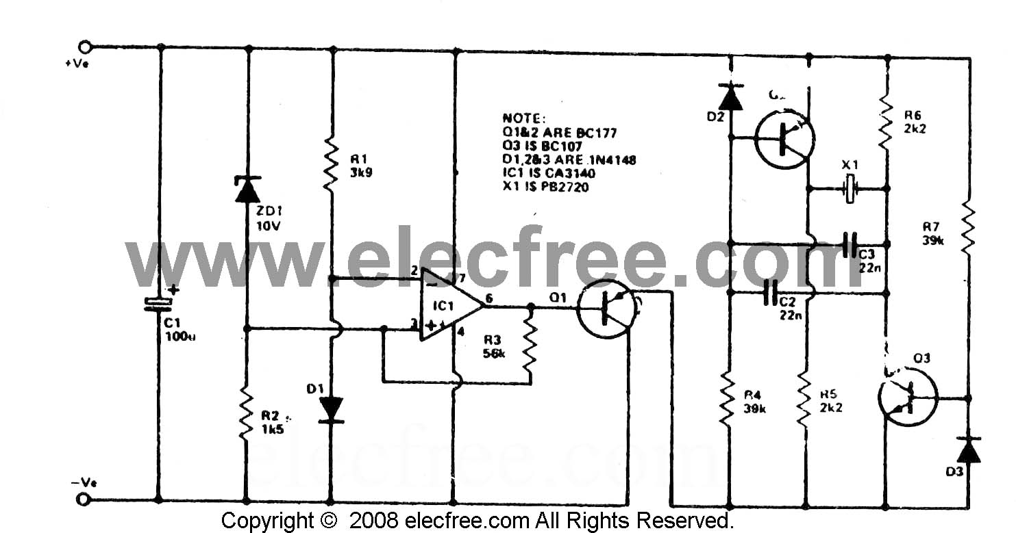
To check the battery in a car, an easy circuit utilizing the IC CA3140 and a transistor is employed. The voltage level of an automobile battery is influenced by many factors, and if it is high... The circuit for checking...
This design is based on one published by Milan Lulic in the German magazine elektroModell. Mr. Lulic's design is for surface mount technology (SMT) construction, whereas mine uses standard off-the-shelf components, and is therefore better suited to construction by...
Lead acid battery charger schematic using IC LM317. This lead acid battery charger circuit is simple to build and can be fit in a small box. The lead acid battery charger circuit utilizing the LM317 integrated circuit (IC) is a...
The circuit described utilizes a quad voltage comparator (LM339) to function as a simple bar graph meter that indicates the charge status of a 12-volt lead-acid battery. A 5-volt reference voltage is employed for this purpose. The circuit leverages the...
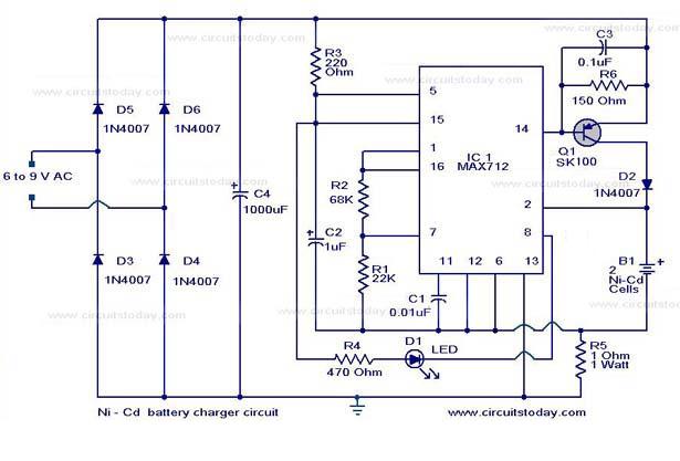
The following circuit illustrates a super fast Ni-Cd battery charger. It is based on the IC MAX 712 and is designed to charge a Ni-Cd battery at a rate of 300 mA. The circuit utilizes the MAX 712 integrated circuit,...
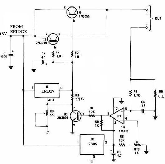
This universal battery charger utilizes the LM317 voltage regulator and features an adjustable output voltage along with a constant-current charging circuit, making it suitable for charging most NiCad batteries and various other battery types. The LM317 universal battery charger...
Warning: include(partials/cookie-banner.php): Failed to open stream: Permission denied in /var/www/html/nextgr/view-circuit.php on line 713
Warning: include(): Failed opening 'partials/cookie-banner.php' for inclusion (include_path='.:/usr/share/php') in /var/www/html/nextgr/view-circuit.php on line 713