
lead acid battery charger circuit

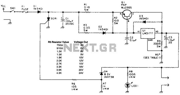
The lead acid battery charger circuit utilizing the LM317 integrated circuit (IC) is a practical solution for charging lead acid batteries. The LM317 is a versatile adjustable voltage regulator that can be configured to provide a stable output voltage suitable for charging. This circuit design is characterized by its simplicity, making it accessible for both novice and experienced electronics enthusiasts.
The schematic typically includes the LM317 IC, several resistors, capacitors, and diodes to ensure proper voltage regulation and filtering. The output voltage can be adjusted by changing the values of the resistors connected to the adjustment pin of the LM317. A common configuration involves using a 240-ohm resistor in series with a variable resistor, allowing for fine-tuning of the output voltage to match the specifications of the lead acid battery being charged.
Additionally, the circuit may incorporate a heat sink for the LM317 to dissipate heat generated during operation, which is crucial for maintaining performance and longevity of the IC. A diode may also be placed in parallel with the battery to prevent reverse current flow, which can damage the charger or battery when the charger is turned off.
The overall compact design allows for the charger to be housed in a small enclosure, making it suitable for portable applications. This simplicity and effectiveness make the LM317-based lead acid battery charger a valuable project for those looking to charge lead acid batteries safely and efficiently.Lead acid battery charger schematic using IC LM317. This lead acid battery charger circuit is simple to build and can be fit in a small box. .. 🔗 External reference
Related Circuits
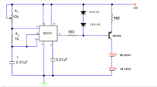
A TV remote jammer circuit using the NE555 timer IC. This device allows users to watch their favorite TV channels without interruptions, as it prevents others from changing the channel using a remote control when the circuit is activated....
For a robot to perform its assigned tasks, a controller is necessary. This controller may be mechanical, electrical, electronic, or a combination of these. It acts as the brain of the entire system, providing the robot with its intelligence....
A laptop computer power supply that provides a 9-V output, includes crowbar overvoltage protection, and operates from a 12-V input supply is described. The input supply voltage must be at least 3.6 V above the desired output voltage. The...
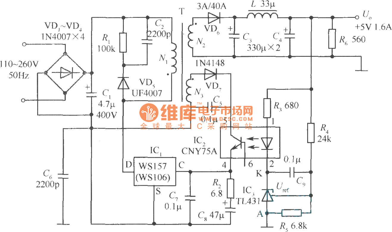
The +5V, 1.6A precision switching power supply circuit is depicted in the figure. This circuit utilizes a photoelectric coupler (CNY75A) and an adjustable precision parallel regulator (TIA31). R3 serves as the current limiting resistor, while R4 and R5 function...
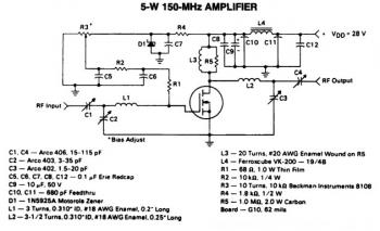
This is a 5W -150MHz RF amplifier circuit that utilizes the MRF123 TMOSFET. The MRF123 is a high-gain FET which may exhibit instability at both VHF and UHF frequencies; therefore, a 68 Ohm input loading resistor is employed to...
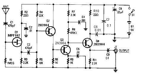
A simple active antenna can be designed using this electronic circuit diagram. This active antenna utilizes transistors and a few common electronic components. In the practice of short-wave frequency reception, a general rule is that a longer antenna will...