
Motor Speed Control with Battery Eliminator Circuit
This electronic control design, inspired by Milan Lulic's work, is tailored for hobbyists utilizing conventional components rather than surface mount technology (SMT). The compact dimensions of the control unit, measuring 1.3 inches in length, 1.1 inches in width, and 0.7 inches in height, make it suitable for various applications where space is a constraint. Weighing approximately 0.5 ounces (14 grams) without the motor and battery leads, the design is lightweight, facilitating easy integration into projects.
The control is engineered to handle a continuous current of 12A, with the capacity to manage intermittent loads of up to 18A. This capability makes it versatile for powering different types of motors or electronic devices that may require varying levels of current during operation. The voltage loss specification of 120mV indicates the efficiency of the control unit in maintaining power delivery, minimizing energy loss during operation.
To implement this design, the schematic should include standard components such as resistors, capacitors, diodes, and transistors, which can be easily sourced. The layout should ensure proper heat dissipation and include adequate filtering to reduce noise in the control signals. Additionally, the PCB (Printed Circuit Board) design should accommodate the specified dimensions while providing clear pathways for current flow and minimizing interference between components.
Overall, this control design offers a practical solution for hobbyists looking to create efficient and reliable electronic projects without the complexities associated with SMT construction. The specifications provided ensure that the control can be effectively utilized in various applications, contributing to its appeal among DIY electronics enthusiasts.This design is based on one published by Milan Lulic in the German magazine elektroModell. Mr. Lulic`s design is for surface mount technology (SMT) construction, whereas mine uses standard off-the-shelf components, and is therefore better suited to construction by the hobbyist. This control has the following specifications: Size: 1.3"L x 1.1"W x 0.7"H (3.3cm x 2.8cm x 1.5cm). Weight: approximately 0.5 oz (14g) without motor and battery leads. Current: 12A continuous, 18A intermittent. Voltage Loss: 120mV @ 🔗 External reference
Related Circuits
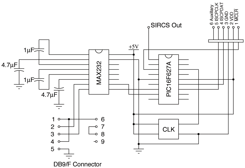
Since building a MythTV, the need for DVD and VCR remote controls was eliminated. However, control over the television remained necessary for functions such as power, volume, mute, and video input selection. Initially, there was uncertainty regarding serial control...
Switch mode circuits can implement a lead acid battery charger more efficiently. It can be constructed using the bq24105 battery charger controller. Switch mode power supplies (SMPS) are widely recognized for their efficiency and compactness, making them suitable for applications...
The 5W/6V solar panel can achieve a maximum current of approximately 500 to 800mA, peaking at 800mA during noon. Limiting the current to 150mA appears inefficient. A 1W panel can supply around 160mA during peak performance for up to...
Security is a prime concern in our day-to-day life. Everyone wants to be as much secure as possible. An access control for doors forms a vital link in a security chain. The Microcontroller based Home Security System can be...
The 555 is wired as an astable and the capacitor is charged only through the 4.7Kohm trimmer (notice the diode) and discharged only through the 2.2 Kohm trimmer, making the duty cycle fully adjustable. The square wave is then...
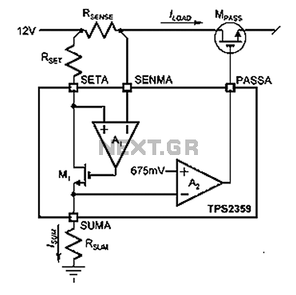
Amplifier A1 utilizes the voltage across the sense resistor sensors to monitor the load current ILOAD. The power management channel employs a similar circuit, with the distinction of integrating resistors RSENSE and RSET. Amplifier A1 is configured to measure the...