
Battery Indicator
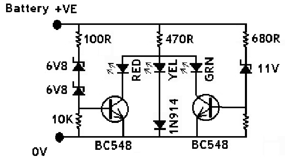
The circuit described employs several crucial components including the IN914 diode, zener diodes, and various colored LEDs, each serving a specific function in the overall operation. The IN914 diode, a standard silicon diode, acts as a rectifier, ensuring current flows in one direction. The zener diodes provide voltage regulation, allowing for stable operation across varying input voltages. The use of different colored LEDs allows for visual feedback corresponding to the voltage levels detected within the circuit.
The transistors Q1 and Q2 play a vital role in controlling the LED states based on the input voltage. Resistors R3 and R5 are essential for setting the biasing conditions of these transistors, ensuring that they only conduct when the input voltage reaches certain thresholds. The feedback mechanism involving the LEDs allows for a clear indication of the circuit's operational state, with the yellow LED indicating low voltage conditions, the green LED indicating an intermediate voltage range, and the red LED representing high voltage conditions.
The circuit's design emphasizes efficiency and reliability, utilizing components that are readily available and easy to implement. The careful selection of voltage thresholds for the zener diodes and the corresponding LED behaviors ensures that the circuit operates effectively across a range of input conditions, making it suitable for applications in vehicle battery monitoring systems and other similar electronic projects. This comprehensive arrangement of components and their interactions illustrates a well-thought-out schematic that balances functionality with simplicity.The IN914 (little glassy diode) and the zener diodes all have bands on the body which must be put in the direction shown on the drawing. The bands ar ` e at the K end of the diodes. A magnifying glass will help to locate the bands and also to check the values of the zeners. To identify them, the following procedure will help : with a magnifying glass find the diode that` has the code IN4148 printed on the glassy surface. This is the silicon diode usually referred to as IN914, NOT a zener. The zeners may have their voltage printed on the side, or they may have numbers. Remember that there are two 6V8 zeners and one 11V, so 4. The molex pins are to connect the wires to the circuit. Push them through in their holes and solder. Bare the Red and Black hook-up wires, tin them and solder to the pins. Red is Positive, Black Negative 5. Connect the circuit to a power supply with a variable Voltage control, but make sure the polarity is co ect. Wind up the voltage and check the performance of your circuit against the quoted performance figures.
This circuit depends for its operation upon the different voltage drops across different colour LEDs. At 20mA the voltage drops across red, yellow and green LEDs are typically 1. 7, 3. 0 and 2. 3 volts respectively. When the vehicle battery voltage is too low to cause either ZDI/ZD2 or ZD3 to conduct, Q1 and 02 are held off by R3 and R5.
Under these conditions the yellow LED is forward biased and conducts `via D1 producing a potential of about 3. 7 volts at the "A legs" of the LED`s. When the supply rises above about 11. 6 volts ZD3 conducts, biasing Q2 on. By virtue of its lower voltage recuirements the green LED conducts, reducing the voltage at the "A legs" of the LED`s to approximately 2.
6 volts. This is not enough to bias DI/LED2 on, so the yellow LED goes off. The green LED `steals` the bias from the yellow LED. When thesupply rises above about 14. 2 volts, Q1 is biased on and the red LED `steals` the bias from the green. The potential at the "A legs" of the LED`s falls to two volts and only thered LED conducts. 🔗 External reference
Related Circuits
A straightforward method for charging a battery using a higher voltage source is illustrated in the accompanying circuit diagram. The circuit requires only one resistor to establish the desired charging current, which can be determined by dividing the voltage...
A logic indicator circuit, also known as a logic probe, is utilized to identify the logic level at any point within a logic circuit. The indicator can be visual, employing components such as LEDs, LCDs, or seven-segment displays. The logic...
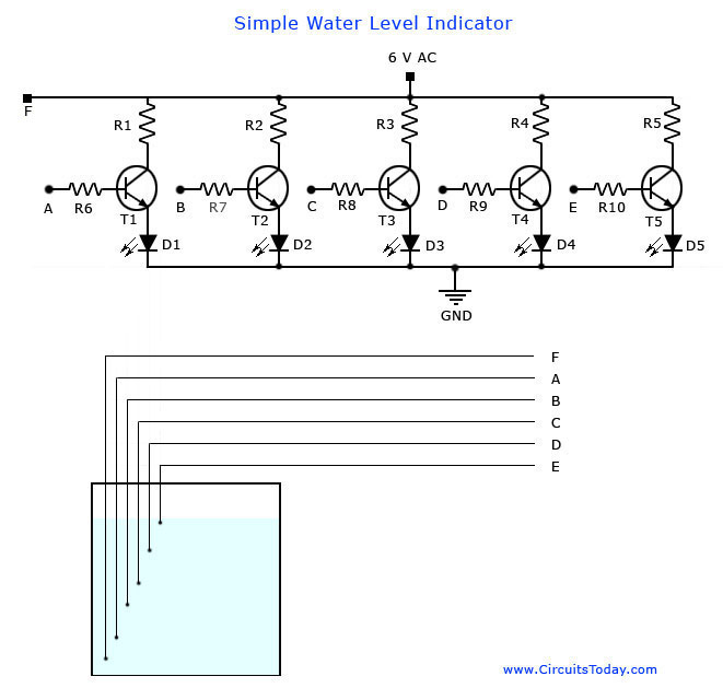
A simple water level indicator project with a circuit diagram for home and industry. This water tank level sensor can be utilized for any liquid level indicator projects. The water level indicator circuit is designed to monitor and display the...
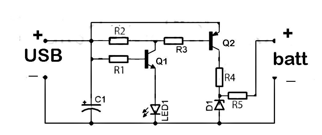
This document discusses the series used in USB connections for charging batteries. The output voltage ranges from 4.7 volts to 5 volts DC, which is suitable for charging mobile phones and other battery types. The circuit described enhances the...
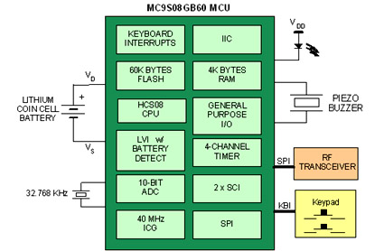
Battery-powered devices, such as electric toothbrushes, shavers, cell phones, PDAs, MP3 players, and remote controls, are integral to daily life. Consequently, power management has become a critical consideration for embedded designers. Microcontrollers (MCUs) provide various methods for managing power...
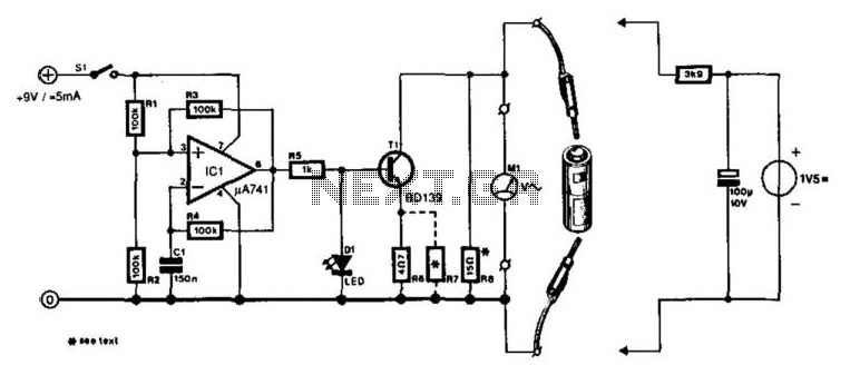
A designer often needs to know the internal resistance value of a battery. Many testers provide a relative indication of this value, but it is seldom expressed in ohms. The current tester can, in principle, provide this information. The...