
Audible Logic Probe/Indicator

The logic indicator circuit serves as an essential tool for troubleshooting and analyzing digital circuits. It typically consists of a voltage divider, a comparator, and a visual output component. The voltage divider scales the input voltage to a manageable level, while the comparator compares this voltage against a predefined threshold to determine the logic level—high or low.
For visual indication, the circuit can incorporate different types of displays. An LED may light up in response to a high logic level, while an LCD can provide more detailed information about the logic state. A seven-segment display can be used to show binary values or specific logic levels in a more user-friendly format.
The design may include additional features such as a built-in buzzer for audible alerts or a switch to toggle between different voltage ranges, enhancing its versatility. The circuit can be powered by a battery or an external power source, ensuring portability and ease of use in various environments.
In summary, the logic indicator circuit is a vital instrument in electronic diagnostics, providing clear visual feedback on the state of logic signals, thus facilitating efficient circuit analysis and debugging.Logic indicator circuit / logic probe is used to identify logic level at any point of logic circuitry. The indicator can be visual (using LED, LCD, of 7. 🔗 External reference
Related Circuits
The 741 operational amplifier is configured as an audio oscillator utilizing Radio Shack 276-677 photocells within the feedback circuit. When light illuminates PC1, its resistance diminishes, leading to a corresponding decrease in the frequency of the audio tone heard...
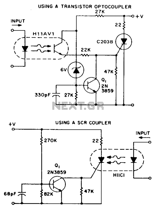
These two simple circuits provide zero voltage switching. They can be used with full wave bridges or in antiparallel to provide full wave control and are normally used to trigger power thyristors. If an input signal is present during...
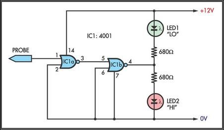
This simple logic probe has both LEDs illuminated with no signal at the input. However, due to the NOR gates connected to the probe, it indicates correctly when a high or low signal is present. It also functions correctly...

The schematic below illustrates four methods of controlling a relay with a digital logic signal. Figure A can be used in most cases where the relay coil requires 100 mA or less and the input current is 2 milliamps...
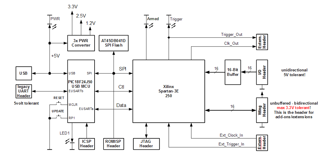
The Openbench Logic Sniffer is an open-source logic analyzer designed to support the SUMP logic analyzer software at minimal cost. Source and design files can be downloaded from the Gadget Factory project page. This project originated from discussions in...
The circuit diagram illustrates a five-use tri-state audio logic pen utilizing components such as the CD4066 and a 555 timer. The primary elements include a multivibrator, a four-way switch (CD4066, designated as IC1), and a gate circuit formed by...