
constant current battery charger
The circuit operates by connecting a higher voltage battery in parallel with the battery to be charged. The resistor plays a crucial role in controlling the current flowing into the charging battery. To calculate the appropriate resistance value, the voltage difference between the source battery and the target battery is measured. This voltage difference is then divided by the desired charging current to obtain the resistance value using Ohm's Law (R = V/I).
For instance, if the higher voltage battery is at 12V and the battery being charged is at 6V, the voltage difference is 6V. If the desired charging current is 1A, the required resistance would be R = 6V / 1A = 6 ohms. This resistor must be rated to handle the power dissipation, which can be calculated using the formula P = I^2 * R. In this case, P = (1A)^2 * 6Ω = 6W, so a resistor rated for at least 10W would be advisable to ensure reliability and prevent overheating.
Additionally, it is essential to consider the specifications of both batteries to ensure safe charging. The charging process should be monitored to prevent overcharging, which can lead to battery damage or reduced lifespan. Implementing a diode in series with the charging circuit can prevent reverse current flow when the higher voltage battery is disconnected, thereby protecting the charged battery.
Overall, this simple charging circuit is effective for applications where a higher voltage source is available, and it can be easily modified to accommodate different voltage and current requirements by adjusting the resistor value accordingly.A simple method of charging a battery from a higher voltage battery is shown in the circuit below to the left. Only one resistor is needed to set the desired charging current and is calculated by dividing the difference in battery voltages by the charge current..
🔗 External reference
Related Circuits
A current loop transmitter refers to a sensor system utilized in industrial 4-20mA current loop technology. This transmitter contains the... A current loop transmitter is a critical component in industrial automation and control systems, particularly in applications where analog signal...
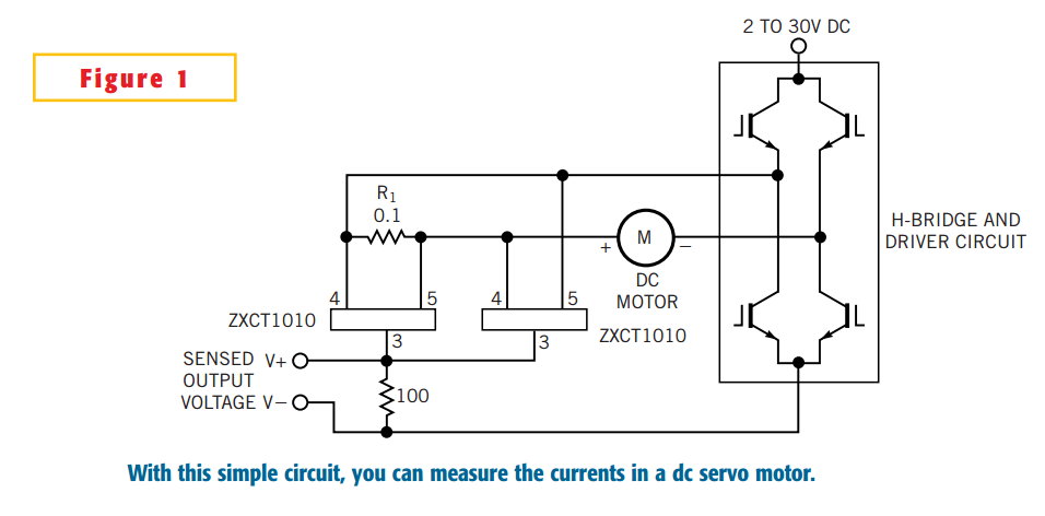
The simple circuit design in Figure 1 lets you measure all components of a current flowing in a dc servo motor. The rectified output of the circuit uses ground as a reference, so you can measure the output by...
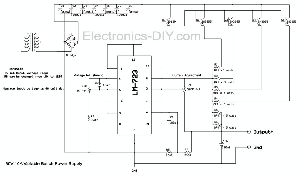
The LM723 current sense and current limit pins (2 and 3) detect a voltage generated by low-resistance current-limiting resistors. When this voltage reaches a specific threshold, the integrated circuit (IC) either shuts down or restricts the power supply output....
This is a discrete high-current switch-mode LED driver circuit. The fundamental principle of this circuit is based on the buck-converter topology. The efficiency of this circuit is 80%. The discrete high-current switch-mode LED driver circuit utilizes a buck converter configuration...

The purpose of this circuit is to maintain a permanent magnet DC motor at a constant speed, which is set externally. This is achieved by monitoring the current flowing through and the voltage across the motor's brushes. The schematic for...
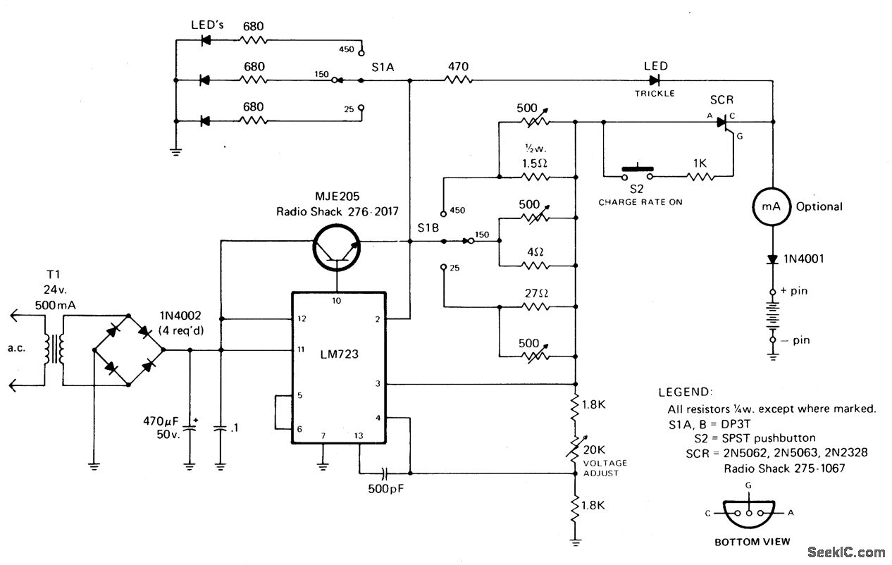
The rectified and filtered voltage from the 24 Vac transformer is applied to the LM723 voltage regulator, along with an NPN pass transistor configured for constant current supply. A 470-ohm resistor limits the trickle current until the momentary pushbutton...