
Battery Tester Circuit

The described circuit employs a constant-current approach, making it suitable for testing various battery types without the need for complex adjustments. The use of a differential amplifier ensures accurate current regulation, while the Schottky diode provides a stable reference voltage, enhancing the circuit's reliability. The inclusion of a FET as a constant-current sink not only stabilizes the circuit under different loading conditions but also protects it from excessive current flow, making it robust against potential damage from high voltage scenarios. The design's capability to operate at low voltages expands its utility for testing smaller batteries, such as button cells, which are commonly found in various electronic devices. Overall, this battery testing circuit represents a practical solution for users seeking to diagnose battery issues efficiently and cost-effectively.Is the battery empty, or is there something wrong with the device That`s always a difficult question when your walkman or some other battery-powered device appears to be dead when you switch it on. Before you take it to the shop for servicing, the first thing you should do is to test the battery or batteries.
Of course, this means you need a reliable battery tester, but it also means you can limit the damage to the cost of a battery or two and a one-time investment of time and money in building a suitable tester. Many commercial battery testers consist of nothing more than a resistor, a simple little meter and a push-button.
Some manufacturers include an even simpler tester with a set of batteries, consisting of a strip of plastic with a layer of some sort of electrically conductive material that changes color when a current grows through it. If you press this strip over the battery between the positive and negative terminals, a fully charged battery will cause a more intense change in color than a partially discharged battery.
Naturally, tests of this sort do not provide especially reliable or accurate results. The idea behind the circuit described here is to load a single battery, a set of batteries connected in series, a rechargeable battery, or even a small button cell with a reasonably constant current and use a separate multimeter or voltmeter module (M1) to check the voltage. A quickly decreasing voltage indicates that the battery or batteries will have to be replaced soon. If a constant-current circuit is used for the load, the current can never too be large and there is no need to make an adjustment for the number of cells.
The constant-current circuit is specially designed to work with a voltage as low as 0. 9 V. It`s quite difficult to make a circuit work at even lower voltages with normal transistors. The active constant-current element is transistor T1. The current through it is held constant by comparing the voltage across resistor R1 in its collector path with a relatively constant reference voltage across diode D1. This comparison is provided by differential amplifier T3/T4. The voltage across diode D1 (a Schottky type) is reasonably constant by nature, but it is also stabilized by using FET T5 as a simple constant-current sink.
T5 also limits the current at relatively high voltages (with several batteries in series). The constant voltage across D1 is transferred to resistor R12 by differential amplifier T1/T2, so a constant current grows through R1 from the battery or batteries being tested. R1 has a relatively low resistance, so this current is larger than the current drawn by the rest of the circuit.
The quiescent current, which incidentally is also reasonab constant, is thus negligible. The test current thus remains reasonably constant while the battery or batteries is/are being tested. The maximum battery voltage that the tester can handle is set by T5, and here it is 30 V. To ensure that T1 does not get too warm at high battery voltages, keep the test as short as possible.
Use a push-button switch as a test switch so the battery being tested cannot be left under load by accident. 🔗 External reference
Related Circuits
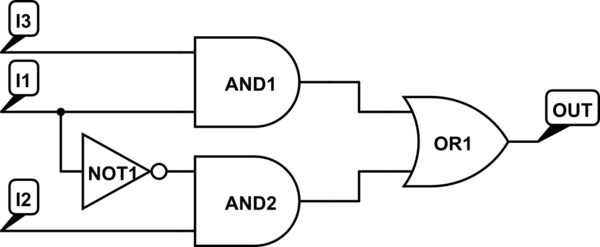
There are integrated circuits that contain AND, OR, and NOT gates. The inquiry revolves around the existence of a single chip that encompasses all the required logic gates. If such a chip does not exist, specific alternatives should be...
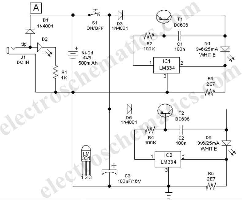
This easy-to-construct handy pen torch electronic circuit has a low component count and utilizes two power white LEDs for illumination. A low voltage (4.8V DC) supply is derived from a built-in rechargeable Ni-Cd battery pack and is converted into...
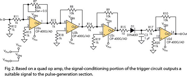
This version of the trigger circuit for the stop-motion camera system utilizes an electret microphone for sonic input, although it can be replaced with an LED and photodiode pair for optical triggering. A recent home-built project involved constructing a...
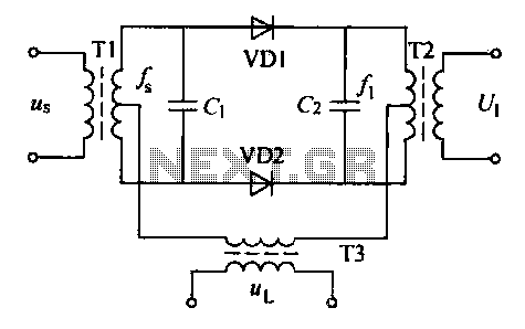
A balanced diode mixer circuit is presented, utilizing two diodes, specifically the 2AP9 model. The circuit operates with a high voltage, causing the diodes to function in an off state, which is also referred to as a diode switch...
A bridge rectifier capacitor filter serves as a primary power supply for current amplifier circuits. This power supply configuration is straightforward and offers enhanced performance. The bridge rectifier circuit is a full-wave rectifying circuit, meaning it converts both the...
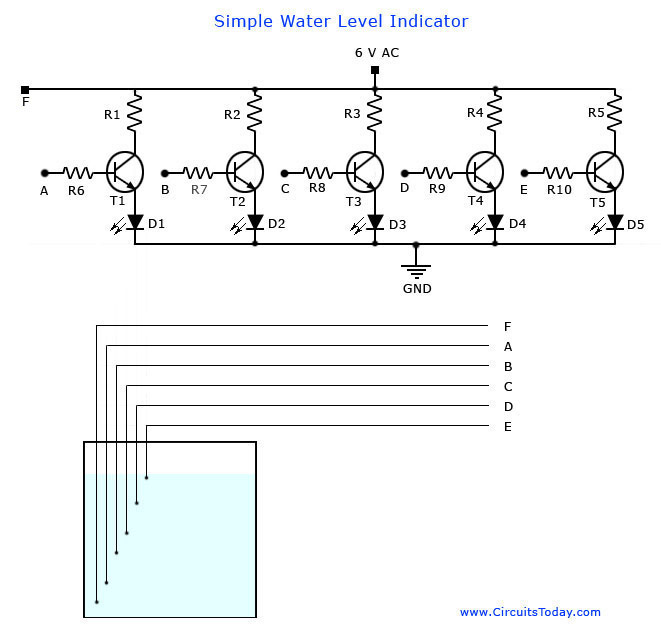
A simple water level indicator project with a circuit diagram for home and industry. This water tank level sensor can be utilized for any liquid level indicator projects. The water level indicator circuit is designed to monitor and display the...