
Balanced diode mixer circuit

The balanced diode mixer circuit is designed to efficiently combine two input signals while minimizing unwanted interference and maintaining signal integrity. The use of two diodes, such as the 2AP9, allows for the mixing of high-frequency signals. In this configuration, the diodes are arranged in a balanced manner to achieve a low distortion output.
The operation of the circuit relies on the principle of diode switching. When the input signals are applied, the diodes switch between conducting and non-conducting states based on the amplitude of the signals. This switching action allows for the generation of sum and difference frequencies at the output, which are essential in applications such as radio frequency (RF) communications and signal processing.
The balanced design helps to cancel out common-mode signals and enhances the performance of the mixer by providing better isolation between the input and output. This results in improved linearity and reduced intermodulation distortion, which is crucial for maintaining the quality of the mixed signals.
In summary, the balanced diode mixer circuit employing the 2AP9 diodes operates effectively under high voltage conditions, utilizing the switching characteristics of the diodes to achieve optimal signal mixing while minimizing distortion and interference. The circuit is particularly valuable in RF applications where signal integrity is paramount.Balanced diode mixer circuit is shown. Diode 2AP9 2. Due to the use of two diodes and the voltage is large, the diode operates in the off state, it is also known diode switch tube balanced mixer.
Related Circuits
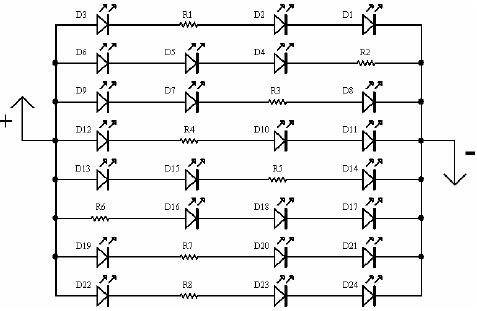
A light-emitting diode (LED) lamp is a solid-state lighting device that utilizes light-emitting diodes as its light source. LEDs are a cost-effective and convenient choice for various lighting applications. They are available in an extensive range of colors, styles,...
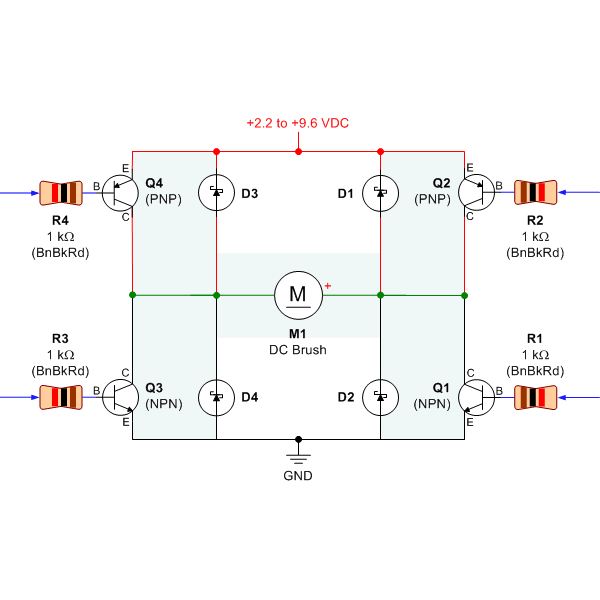
Selecting the appropriate DC motor is essential for constructing mobile robots. Testing DC motors is straightforward and can be accomplished by assembling a basic DC motor circuit. The components needed for this circuit include a DC motor, a battery...
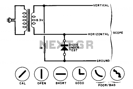
The circuit will display curves on an oscilloscope, depending on the state of the diode. To calibrate, replace the diode with a 1000-ohm resistor and adjust the oscilloscope gains for a 45-degree line. The drawings illustrate some expected results. The...
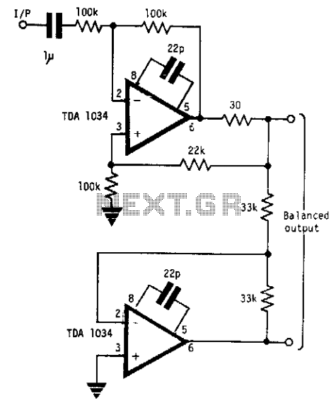
This circuit will handle +24 dBm with ± 12 volts supply using TDA 1034s. This circuit uses current and voltage feedback. The described circuit utilizes the TDA 1034S integrated circuit, which is designed for audio applications and can handle an...

This circuit exhibits an exceptionally fast high-frequency response, as demonstrated by applying a 100 kHz square wave to the input. All graphs were produced using Tina Pro. The circuit's design is optimized for high-frequency applications, showcasing rapid response times that...
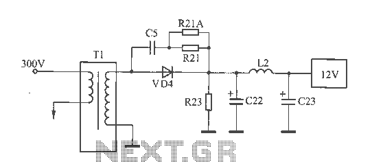
The 12V voltage instability should first be investigated by checking the output section of the switching power supply, as illustrated in the accompanying figure. The secondary winding of the transformer and the switch VD4 have been examined and found...