
Battery Tester Circuit Schematic
The described battery tester circuit is an effective solution for assessing battery health in various applications. It is particularly useful for users who frequently utilize battery-powered devices, as it provides a more accurate assessment of battery condition compared to simpler methods. The use of a constant-current load ensures that the test results are consistent and reliable, making it easier to determine the state of the battery. The design emphasizes safety and efficiency, allowing for quick testing without risking damage to the components involved. Ultimately, this circuit can save users time and money by enabling them to identify battery issues promptly and avoid unnecessary repairs or replacements of functioning devices.Is the battery empty, or is there something wrong with the device That`s always a difficult question when your walkman or some other battery-powered device appears to be dead when you switch it on. Before you take it to the shop for servicing, the first thing you should do is to test the battery or batteries.
Of course, this means you need a reli able battery tester, but it also means you can limit the damage to the cost of a battery or two and a one-time investment of time and money in building a suitable tester. Many commercial battery testers consist of nothing more than a resistor, a simple little meter and a push-button.
Some manufacturers include an even simpler tester with a set of batteries, consisting of a strip of plastic with a layer of some sort of electrically conductive material that changes color when a current grows through it. If you press this strip over the battery between the positive and negative terminals, a fully charged battery will cause a more intense change in color than a partially discharged battery.
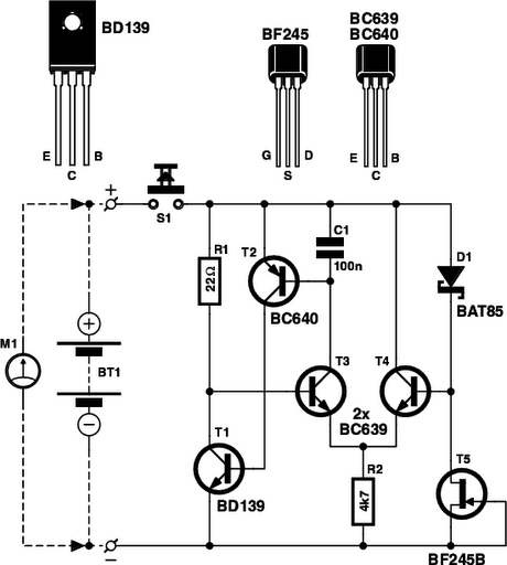
Naturally, tests of this sort do not provide especially reliable or accurate results. The idea behind the circuit described here is to load a single battery, a set of batteries connected in series, a rechargeable battery, or even a small button cell with a reasonably constant current and use a separate multimeter or voltmeter module (M1) to check the voltage. A quickly decreasing voltage indicates that the battery or batteries will have to be replaced soon. If a constant-current circuit is used for the load, the current can never too be large and there is no need to make an adjustment for the number of cells.
The constant-current circuit is specially designed to work with a voltage as low as 0. 9 V. It`s quite difficult to make a circuit work at even lower voltages with normal transistors. The active constant-current element is transistor T1. The current through it is held constant by comparing the voltage across resistor R1 in its collector path with a relatively constant reference voltage across diode D1. This comparison is provided by differential amplifier T3/T4. The voltage across diode D1 (a Schottky type) is reasonably constant by nature, but it is also stabilized by using FET T5 as a simple constant-current sink.
T5 also limits the current at relatively high voltages (with several batteries in series). The constant voltage across D1 is transferred to resistor R12 by differential amplifier T1/T2, so a constant current grows through R1 from the battery or batteries being tested. R1 has a relatively low resistance, so this current is larger than the current drawn by the rest of the circuit.
The quiescent current, which incidentally is also reasonab constant, is thus negligible. The test current thus remains reasonably constant while the battery or batteries is/are being tested. The maximum battery voltage that the tester can handle is set by T5, and here it is 30 V. To ensure that T1 does not get too warm at high battery voltages, keep the test as short as possible.
Use a push-button switch as a test switch so the battery being tested cannot be left under load by accident. 🔗 External reference
Related Circuits
This circuit provides a visual 9 second delay using a 7 segment digital readout LED. When the switch is closed, the CD4010 up/down counter is preset to 9 and the 555 timer is disabled with the output held high....
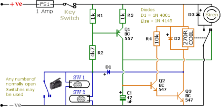
The schematic illustrates a Simple Motorcycle Alarm Circuit Diagram created by Ron J. It incorporates micro-switches to safeguard removable panels and... The Simple Motorcycle Alarm Circuit Diagram is designed to enhance the security of motorcycles by utilizing a series of...
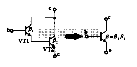
There are two composite pipe configurations: one consists of two transistors of the same type, while the other is made up of two different types of pipe configurations. The first configuration, utilizing two transistors of the same type, typically involves...

The microprocessor utilizes a linear regulator power circuit that is constructed using two MAX666 devices. The power supply for the CPU and A/D converter is connected to A2, while the RAM and real-time clock receive power from A1. The...
The TX05C-R infrared surveillance alarm circuit is designed for monitoring walls, windows, doors, and various restricted areas. When an intrusion occurs, the alarm activates to enhance security. The circuit comprises a transmitter module, a receiver module, a time-base circuit,...
This circuit diagram illustrates the conversion of a speaker into a microphone. When sound waves impact the diaphragm of a speaker, fluctuations occur in the coil, generating an induced voltage. This induced voltage is typically substantial but low in...