
Battery voltage monitor circuit by LM339
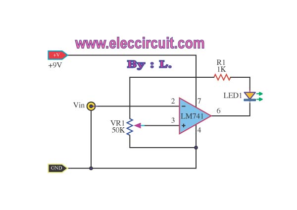
The low voltage tester circuit is designed to provide a reliable method for monitoring the voltage levels of batteries and other power sources. The circuit typically includes a voltage divider, which scales down the voltage to a level that can be safely processed by a microcontroller or comparator.
An LED display is incorporated to visually indicate the voltage status. It may consist of multiple LEDs, each representing a specific voltage range, allowing for quick assessment of the battery's condition. When the voltage falls below a predetermined threshold, an alarm sound is triggered, alerting the user to potential issues with the power source.
Powering the circuit can be achieved through the battery being tested or an external power supply. The use of low-power components ensures that the circuit does not significantly drain the battery being monitored.
Additional features may include a reset button to silence the alarm and reset the display, as well as calibration options to adjust the voltage thresholds according to different battery types. This circuit is suitable for a variety of applications, including testing household batteries, automotive batteries, and other low-voltage power supplies.
Overall, this low voltage tester circuit is an essential tool for ensuring the reliability and performance of various voltage sources in electronic applications.This simple low voltage tester circuit can be used to monitor battery and other voltage sources of current for problems, by LED display and alarm sound. Which.. 🔗 External reference
Related Circuits
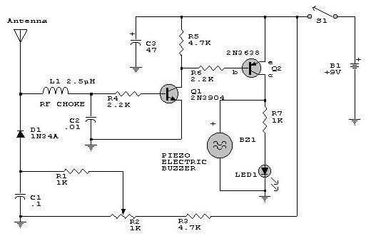
This electronic RF detector project is constructed using common transistors and a few standard electronic components. The RF detector is capable of responding to RF signals below the standard broadcast band and extending to over 500 MHz, providing both...
This is a high-power LED driver circuit designed to accommodate a wide input-voltage range. The circuit utilizes a buck/boost converter controller to regulate the current supplied to a white LED. The high-power LED driver circuit is engineered to effectively manage...
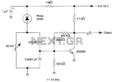
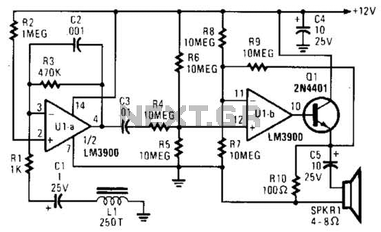
The circuit utilizes a tuned circuit for frequency selection, designed to operate at approximately 51 kHz. The 2N3565 transistor amplifies the output generated by the tuned circuit. The described circuit operates on the principle of resonance, where the tuned circuit...
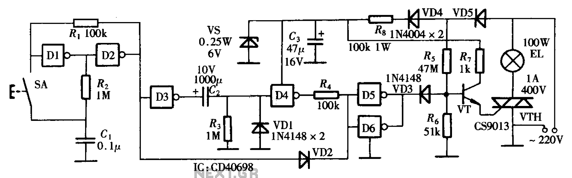
The bedside door fixture delay circuit features a straightforward design and offers cost-effectiveness. It is constructed using a hex inverter CD4069. The bedside door fixture delay circuit employs the hex inverter CD4069, which is a versatile integrated circuit (IC) commonly...
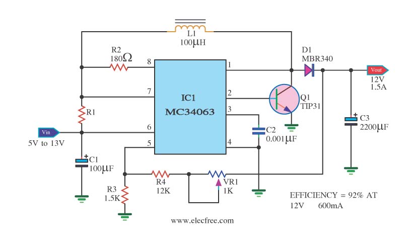
The circuit is a battery-powered voltage regulator that outputs 12V at 1.5A. It accepts an input voltage range from 5V to 13V. The circuit utilizes the MC34063 integrated circuit, making it a straightforward design. The circuit primarily functions as a...
This caller ID circuit utilizes the Motorola MG145447 IC chip. The service must be available from your local phone company for this circuit to function properly. The caller ID circuit based on the Motorola MG145447 IC chip is designed to...
Warning: include(partials/cookie-banner.php): Failed to open stream: Permission denied in /var/www/html/nextgr/view-circuit.php on line 713
Warning: include(): Failed opening 'partials/cookie-banner.php' for inclusion (include_path='.:/usr/share/php') in /var/www/html/nextgr/view-circuit.php on line 713