
RF detector electronic project circuit design using 2N2222 transistors
This RF detector circuit is a versatile tool for various applications, including amateur radio, signal analysis, and educational projects. The design incorporates a straightforward configuration that allows for easy assembly and troubleshooting. The use of common transistors such as the 2N3906 and PN2222A ensures that the circuit can be built with readily available components.
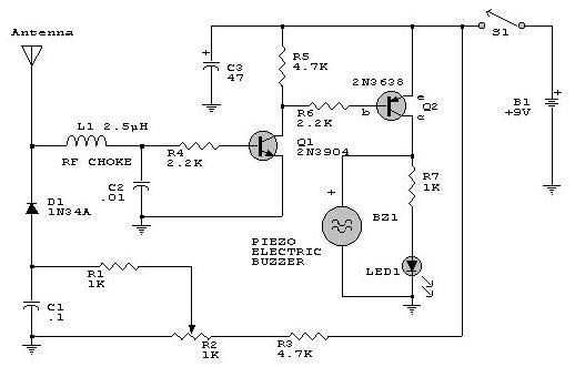
The circuit operates by first capturing RF signals through an antenna, which feeds into the detector diode. The diode rectifies the RF signal, converting it into a DC voltage that can be processed by the following stages. The biasing of diode D2, adjusted using potentiometer R2, is critical for optimizing the sensitivity of the detector. This adjustment allows the circuit to effectively respond to a wide range of signal strengths, ensuring reliable operation under varying conditions.
For enhanced performance, particularly in low-signal environments, the addition of a wideband RF amplifier between the antenna and the detector diode is recommended. This amplifier boosts the incoming RF signals, improving the overall sensitivity of the detector. Careful layout considerations, such as keeping the leads of the diode and capacitor (C1) short, help reduce stray inductance, which can adversely affect performance.
The visual indication of signal reception can be implemented using an LED, while an audible indication can be achieved with a small speaker or piezo buzzer. This dual-indication system allows the user to easily identify the presence of RF signals, making the circuit practical for field use.
In summary, this RF detector circuit is a compact and effective solution for detecting a wide range of RF signals, with straightforward adjustments for sensitivity and easy integration of additional components for enhanced performance.This electronic rf detector electronic project is designed using common transistors and other few common electronic parts. This rf detector responds to RF signals bellow the standard broadcast band to well over 500 MHz and provides an visual, and audible indication when the signal is received.
By adjusting the bias of D2 with the R2 potentiomete r the circuit can detect low power or strong signals. The circuit can be powered using a simple 9 volts battery or any other 9 volts DC power supply circuit. If the rf detector is not enough sensitive you can connect a good wideband RF amp between the antenna and the detector diode.
Keep diode and capacitor (C1) leads short to minimize stray inductance. The used transistors can be : 2N3906, 2N2907 or other PNP high gain transistor for Q2 and PN2222A, 2N3904 or other NPN high gain transistor for Q1. 🔗 External reference
Related Circuits
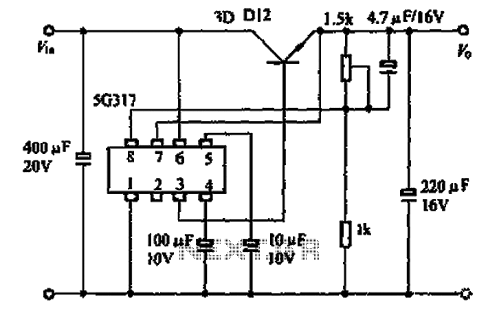
The 5G317 is an integrated voltage regulator circuit used in wiring applications for televisions. The maximum input voltage for the 5G317 should be less than 25V, while the output voltage ranges from 10V to 18V. The maximum output current,...
This circuit is a simple analog multiplier. The operation of the circuit can be understood by considering A2 as a controlled gain amplifier. It involves components such as an analog multiplier, a log-antilog circuit, and a summing junction, along...

Have an old hard drive that no longer works? As long as it still spins up chances are you could build a clock out of your old hard drive! You will need some electronic knowledge, some common electronic components...

This is a VU meter circuit featuring 10 LEDs. This simple LED VU meter consists of only a few components, yet it serves as an effective indicator for sound levels. The circuit is constructed around an unspecified component. The VU...
The goal is to transmit additional information through the use of articles. If there are any issues related to article content, copyright, or other concerns, please contact us via email at [email protected] within 15 days. The content will be...
The saying goes "dead ringworm surgical, medical dead asthma." This example describes an electronic anti-asthmatic device that produces high-voltage stimulation pulses, which can serve as an adjunct therapy for patients suffering from cough. The circuit consists of a self-excited...
Warning: include(partials/cookie-banner.php): Failed to open stream: Permission denied in /var/www/html/nextgr/view-circuit.php on line 713
Warning: include(): Failed opening 'partials/cookie-banner.php' for inclusion (include_path='.:/usr/share/php') in /var/www/html/nextgr/view-circuit.php on line 713