
BC 547 Transistor For Garage Alarm Sensor
The BC 547 transistor is a popular NPN bipolar junction transistor (BJT) that is frequently used in various electronic applications, including alarm systems. In this specific garage alarm sensor circuit, the BC 547 acts as a signal amplifier and switch, allowing for the detection of unauthorized access.
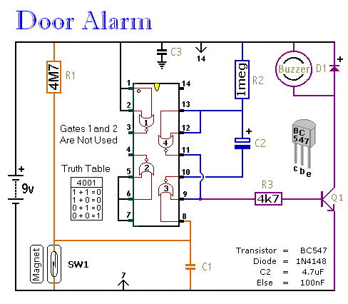
The circuit typically consists of several key components: the BC 547 transistor, resistors, a piezo buzzer or alarm, and a sensor element, which could be a motion detector or a magnetic reed switch. The sensor is responsible for detecting movement or the opening of a garage door. When the sensor is triggered, it sends a small current to the base of the BC 547 transistor.
This small current enables the transistor to conduct, allowing a larger current to flow from the collector to the emitter. As a result, the connected alarm (such as a piezo buzzer) is activated, emitting a sound to alert the homeowner of a potential intrusion.
Resistors in the circuit are used to limit the current flowing to the base of the transistor, ensuring that it operates within safe limits and preventing damage to the components. Additionally, a power supply is necessary to provide the operating voltage for the circuit, typically ranging from 5V to 12V, depending on the specific design requirements.
Overall, the BC 547 transistor garage alarm sensor circuit is an effective and straightforward solution for enhancing security in a garage environment, offering reliable performance with minimal complexity.The following circuit shows about BC 547 Transistor For Garage Alarm Sensor Circuit Diagram. Features: simple single-zone burglar alarm circuit, .. 🔗 External reference
Related Circuits
This is a straightforward and easy-to-assemble multi-purpose alarm system. It can be constructed using stripboard or veroboard along with a few inexpensive, readily available components. The alarm is designed to be installed on doors, windows, sheds, garages, cupboards, and...

This circuit mixer features internal amplification using a 2N3563 transistor. Two input signals can be independently adjusted via VRI and VR2. The VR3 balance control allows for the attenuation of one signal while the other remains active. Additionally, the...
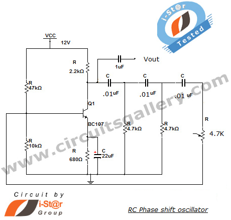
This section introduces a transistor oscillator circuit known as the RC Phase Shift Oscillator. An oscillator is an electronic circuit that functions as a sine wave generator, requiring only a DC power supply. It is commonly used in variable...
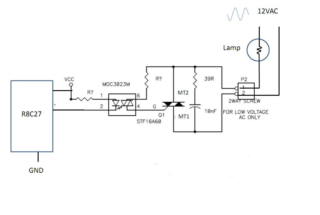
Control 30 incandescent light bulbs with an Arduino Uno on three channels (10 bulbs per channel in parallel). Previous experience involved using an Arduino to control red, green, and blue LEDs with a simple schematic that included three transistors....
The loop can be any type of hookup wire, with a maximum resistance of about 90K. Using very thin wire (40AWG, for example) will create a highly sensitive trip wire, but will reduce the distance it can be strung...
This project involves a light-activated alarm or morning alarm circuit that produces a pleasant melody upon detecting light. To use this circuit as a morning alarm, it should be placed in a location that receives morning sunlight. A 500K...