
morning light activated alarm circuit
The light-activated alarm circuit is designed to provide an auditory alert in response to ambient light levels. The core components include a light-dependent resistor (LDR), which serves as the primary sensor, and the UM66 melody IC, which generates the sound output. The LDR's resistance varies inversely with light intensity; as light increases, the resistance drops, leading to the activation of the BC547 transistor.
The circuit's configuration is as follows: the LDR is connected in a voltage divider arrangement with the 500K variable resistor. This setup allows for precise tuning of the light threshold at which the alarm will activate. The output from the voltage divider feeds into the base of the BC547 transistor, turning it on when the light level exceeds the set point. The collector of the BC547 is connected to the power supply, typically 3V, which is sufficient to power the UM66 IC. The UM66 is specifically designed for melody generation and will produce sound when supplied with the appropriate voltage.
To enhance the audio output, the 2N3904 transistor is used as a sound amplifier. The collector of the 2N3904 connects to the speaker, while its base receives the output signal from the UM66 IC. This configuration allows the circuit to drive an 8-ohm speaker effectively, producing a louder and clearer melody.
For installation, the circuit should be placed in a location where it can receive direct sunlight in the morning. The variable resistor should be adjusted according to the desired sensitivity to light, ensuring that the alarm activates at the preferred light level. This versatility allows the circuit to be adapted for various lighting conditions, making it suitable for different applications beyond just a morning alarm. Overall, this light-activated alarm circuit combines simple components to create an effective and engaging solution for sound-based alerts triggered by light.A very interesting project of a light activated alarm or morning alarm circuit. The circuit will produce a beautiful melody when it will detect light. You can use this circuit as a morning alarm, for this purpose first select a permanent place in your home which gets morning light and then adjust the 500K variable resistor to produce melody on the desired amount of light, after adjusting the desired light level, this circuit will produce melody on the same amount of light every day. You can also use this circuit as light activated alarm for other sources of lights, for this purpose also you have to adjust the 500K variable resistor to produce the melody on the desired amount of light.
The melody circuit is built around the UM66 IC, which is a CMOS IC comes in TO-92 transistor package. Working of the circuit is simple the transistor BC 547 is working as a switch when the LDR detects light its resistance will decrease which will switch on the BC547 transistor and as a result 3 volts start passing through the transistor which will power on the UM66 melody circuit.
The transistor 2N3904 is used to amplify the sound of the melody to drive an 8 Ohms speaker. 🔗 External reference
Related Circuits

This is a simple siren sound generator with high power output and significant noise levels. The circuit utilizes digital integrated circuits (ICs), specifically the CD4046, in an inverter configuration along with four transistors to increase the current output to...

An RF power amplifier is a type of electronic amplifier used to convert a low-power radio-frequency signal into a larger signal of significant power, typically for driving the antenna of a transmitter. It is optimized for high efficiency, high...
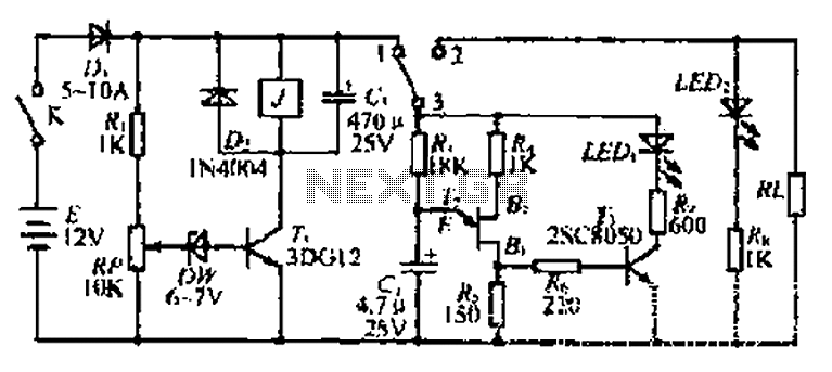
The discharge control circuit consists of a battery management system designed to prevent over-discharge of a battery. It features a relay control mechanism that activates when the battery voltage drops below a specified threshold of approximately 10.5V. The circuit...
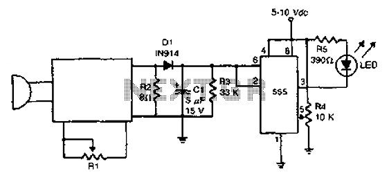
The acoustic detector consists of a Schmitt trigger IC555 connected to various components. When the input exceeds a certain voltage, the output will change state from high to low. R4 is used to set the threshold voltage. The acoustic detector...

One electronic ballast circuit is depicted in Figure 2-11. This circuit utilizes a specialized fluorescent lamp starter thyristor, SCR Y1112, which is superior to ordinary thyristors due to its ability to maintain a higher current value and dU/dt values....
The automatic irrigation control circuit is designed to manage crop irrigation based on soil moisture levels. It is applicable in various agricultural settings, including state farms, orchards, vegetable greenhouses, and large farmland areas. The circuit comprises a soil moisture...