
One transistor audio mixer (2N3563)
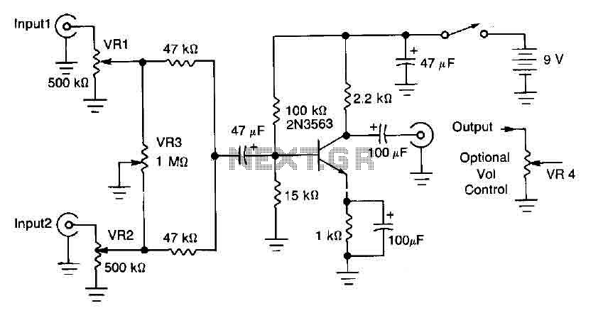
The circuit mixer operates by utilizing the 2N3563 transistor, which serves as the primary amplification component. The two input signals are fed into the mixer, where they can be modified independently using variable resistors VRI and VR2. This flexibility allows for precise control over the amplitude of each signal before they are combined.
The VR3 balance control is critical in this design, as it enables the user to selectively diminish one input signal while maintaining the integrity of the other. This feature is particularly useful in audio applications where blending multiple sound sources is required, allowing for a seamless mixing experience.
The combined output signal's gain is determined by the characteristics of the 2N3563 transistor, which is designed to operate efficiently within the specified frequency range. The output level can be finely tuned using VR4, ensuring that the final mixed signal is at the desired amplitude for further processing or amplification.
Overall, this circuit mixer design is well-suited for applications where precise control over multiple input signals is necessary, providing a robust solution for audio mixing and signal processing needs.This circuit mixer has an internal amplification with 2N3563 transistor. The two input signals can be independently controlled by VRI and VR2. The VR3 balance control is used to remove a signal while the other melted. The transistor provides gain and level of combined output signal is controlled by VR4. 🔗 External reference
Related Circuits
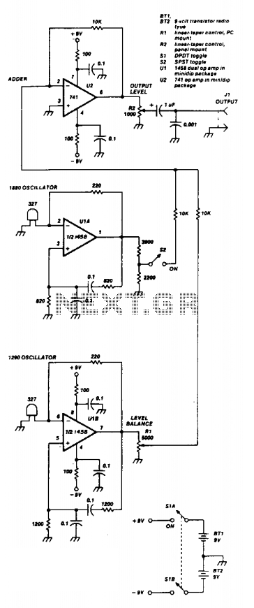
Two 741 operational amplifiers serve as the active components in this Wien bridge oscillator configuration. The dual version of the 741, known as the 1458, can also be utilized. The frequencies of the two oscillators are selected to correspond...
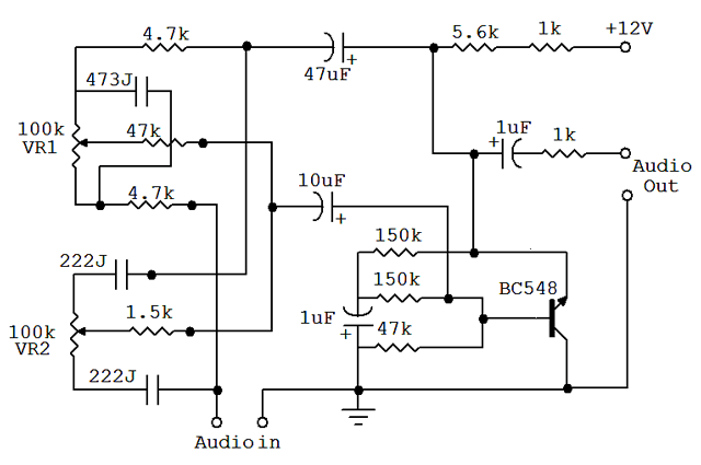
An audio equalizer circuit is utilized to modify the frequency response of an audio signal. This particular equalizer circuit is designed for adjusting the bass and treble (tone) levels of an audio amplifier. To integrate this equalizer circuit with...
This simple, one-transistor amplifier provides a voltage gain of over 1000 (60 dB) for an active aerial impedance crystal earphone. The gain is achieved by replacing the standard load resistor with a constant-current diode that supplies 1/2 mA while...
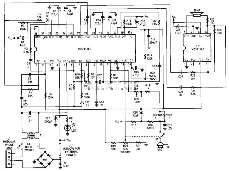
Using a Motorola MC34118 speakerphone IC, this adapter can be utilized with a standard telephone to enable speaker functionality. The device is powered from the phone line; however, it can also be powered through an external power supply if...
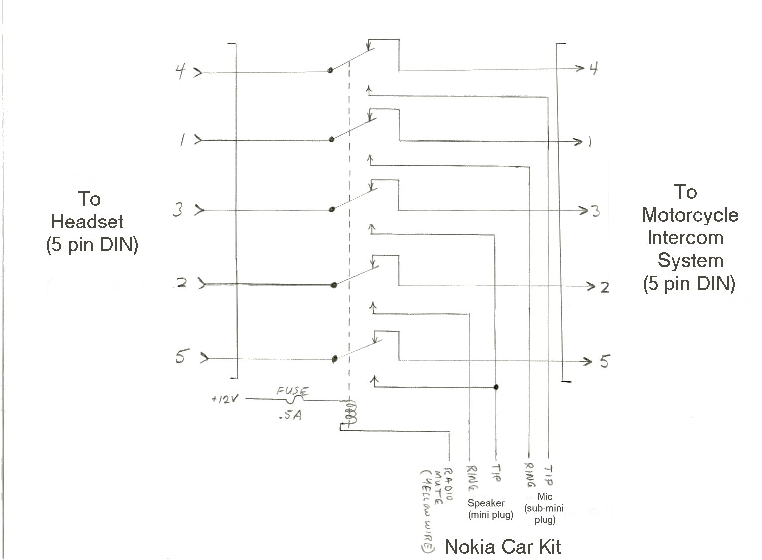
At the time of observation, several units were available on the market, none of which were appealing due to their dependency on specific phones or the requirement for permanent mounting on bicycles. The Kennedy unit, priced around $79.00, was...
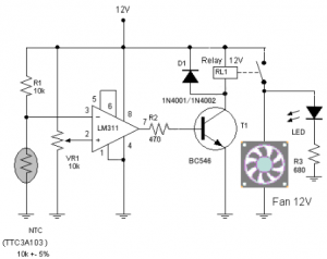
The circuit schematic diagram of a fan speed control system that activates only when necessary. When the transistor heats up, the fan will automatically turn on. The fan speed control circuit operates based on the temperature of the transistor, utilizing...
Warning: include(partials/cookie-banner.php): Failed to open stream: Permission denied in /var/www/html/nextgr/view-circuit.php on line 713
Warning: include(): Failed opening 'partials/cookie-banner.php' for inclusion (include_path='.:/usr/share/php') in /var/www/html/nextgr/view-circuit.php on line 713