
bedside lamp timer schematics
The circuit comprises a dual transistor configuration (Q1 and Q2) that acts as a switch, effectively controlling the power to the load (lamp) and the ICs. The relay, activated by P1, serves as the primary mechanism for switching the circuit on and off. In the initial state, when the circuit is powered, the relay closes, allowing current to flow to the lamp and the integrated circuits. IC2, upon receiving a reset signal at pin 12, begins its oscillation cycle, which is crucial for timing functions within the circuit.
The frequency of oscillation is determined by the RC time constant formed by R4 and C4. The choice of these components directly influences the duration before pin 3 transitions high, which subsequently turns off the entire circuit after the designated time period of approximately 30 minutes. The blinking LED serves as a visual indicator of the operational status of the circuit, providing feedback during the countdown to shutdown. The frequency of the blinking is derived from the output of IC2 at pin 9, which controls the timing of the LED's on-off cycle.
IC1 is configured with two gates in parallel to enhance the current capacity available for driving additional loads, such as a piezo sounder, which can be integrated into the circuit for auditory feedback. This versatility allows for modifications to the circuit based on user requirements. The timing characteristics of the circuit can be easily adjusted by selecting different values for R4 and C4, enabling customization of the operational duration and blinking frequency to suit specific applications.Q1 and Q2 form an ALL-ON ALL-OFF circuit that in the off state draws no significant current. P1 starts the circuit, the relay is turned on and the two ICs are powered. The lamp is powered by the relay switch, and IC2 is reset with a positive voltage at pin 12. IC2 starts oscillating at a frequency set by R4 and C4. With the values shown, pin 3 goe s high after around 30 minutes, turning off the circuit via C3. During the c6 minutes preceding turn-off. The LED does a blinking action by connections of IC1 to pins 1, 2 & 15 of IC2. Blinking frequency is provided by IC2 oscillator at pin 9. The two gates of IC1 are wired in parallel to source more current. If required, a piezo sounder can be connected to pins 1 & 14 of IC1. Obviously, timings can be varied changing C4 and/or R4 values. 🔗 External reference
Related Circuits
This is a programmable clock timer circuit that utilizes individual LEDs to display hours and minutes. Twelve LEDs can be arranged in a circle to represent the twelve hours of a clock face, while an additional twelve LEDs can...
A one-shot multivibrator circuit, commonly referred to as a monostable multivibrator or timer, is designed to generate a pulse strobe of fixed duration in response to an input trigger. The one-shot multivibrator is a fundamental circuit used in various electronic...
A small circuit designed for various time measurement applications. It features an audible sound signal from the buzzer BZ1 and has the capability to drive an external circuit through the optocoupler IC2, once the appropriate circuit is connected to...
This ultra-bright white LED lamp operates on 230V AC with low power consumption. It is suitable for illuminating VU meters, SWR meters, and similar applications. The cost of ultra-bright LEDs available in the market ranges from Rs 8 to...

According to current legislation in many countries, vintage cars must also be fitted with a fog lamp at the rear. In modern cars, there is a bit of circuitry involved in the integration of fog lamps. Fog lamps are essential...
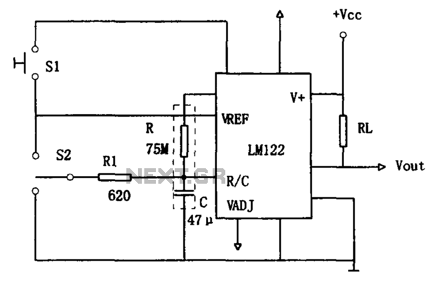
The circuit utilizes an LM122 timer, as illustrated in Figure 1, to manage various timing operations, including starting, resetting, and halting the process midway through. The operation of the circuit is governed by switching mechanisms. Switch S1 initiates the...