
28 LED Clock Timer
The programmable clock timer circuit is designed to provide a visual representation of time using light-emitting diodes (LEDs). The core of the circuit consists of a microcontroller that manages the timing functions and controls the illumination of the LEDs. The microcontroller is programmed to keep track of the current time and to update the LED indicators accordingly.
The inner circle of twelve LEDs represents the hours, with each LED corresponding to one hour on a standard clock face. When the hour changes, the microcontroller activates the LED corresponding to the current hour while turning off the previous hour's LED. This creates a clear visual indication of the current hour.
The outer circle contains twelve additional LEDs, each representing five-minute intervals. As time progresses, the microcontroller keeps track of the minutes and activates the appropriate LED in the outer circle to indicate the current five-minute block. This allows for easy reading of the time in five-minute increments.
Furthermore, within each five-minute interval, four additional LEDs are employed to represent the specific minutes. These LEDs are activated sequentially, illuminating one LED for each minute that passes within the current five-minute block. This feature enhances the precision of the timer, allowing users to see not only the hour and five-minute intervals but also the exact minute.
Power for the circuit can be supplied by a standard DC power source, and appropriate voltage regulation should be implemented to ensure the safe operation of the microcontroller and LEDs. Resistors are also necessary to limit the current flowing through each LED, preventing damage and ensuring longevity.
In summary, this programmable clock timer circuit offers an effective and visually appealing method for displaying time through the use of multiple LEDs, providing a comprehensive overview of hours, five-minute intervals, and minute details. The design is suitable for various applications, including educational tools, decorative clocks, or timers in electronic projects.This is a programmable clock timer circuit that uses individual LEDs to indicate hours and minutes. 12 LEDs can be arranged in a circle to represent the 12 hours of a clock face and an additional 12 LEDs can be arranged in an outer circle to indicate 5 minute intervals within the hour. 4 additional LEDs are used to indicate 1 to 4 minutes of time within each 5 minute interval 🔗 External reference
Related Circuits

Have an old hard drive that no longer works? As long as it still spins up chances are you could build a clock out of your old hard drive! You will need some electronic knowledge, some common electronic components...
The above shows a home-built digital clock that utilizes Nixie tubes for display. Unlike most contemporary Nixie clocks, this design does not employ transistors or integrated circuits for driving the tubes. Instead, the driving logic is constructed using neon...
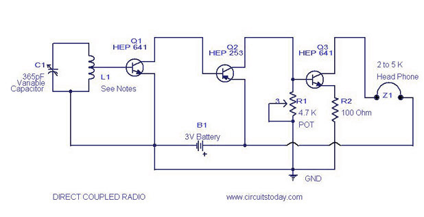
A simple direct-coupled radio circuit diagram and schematic, ideal for adjacent stations. This circuit uses Q1 as an audio amplifier, and the base-emitter capacitance provides radio filtering. The described circuit is a direct-coupled radio receiver designed to effectively operate with...
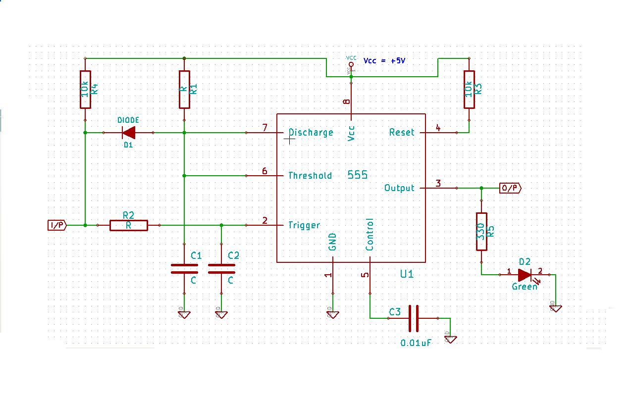
Create a 555 timer-based circuit where the output pin of the 555 timer is held low by default when powered on, and the input pin is held high at power on. The main requirement is that the output pin...
A Super GameBoy was acquired, but it has been observed that the sound pitch is significantly higher than that of an original GameBoy. This discrepancy arises due to a mismatch in CPU clock frequencies: 4.194304 MHz for the original...
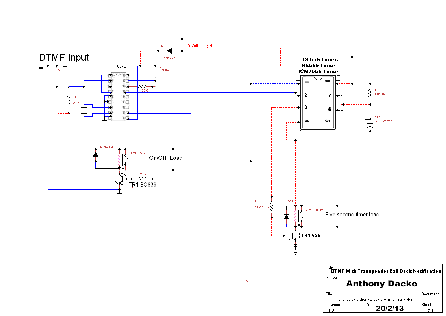
The operation of the circuit is straightforward. When a DTMF tone is sent to the decoder, pin 15 goes high for a brief period, which serves as an effective trigger by supplying a few volts to pin 2 of...