
Beginning Embedded Electronics - 1

Microcontrollers are integral to contemporary electronic systems, serving as the backbone of numerous applications. The ATmega328 microcontroller, for example, is a popular choice for hobbyists and professionals alike due to its balance of performance, ease of use, and affordability. It features 32KB of flash memory, 2KB of SRAM, and 1KB of EEPROM, which provides ample storage for complex applications while allowing for easy modification of the code.
The GPIO pins of the ATmega328 can be configured for various functions, including digital input, digital output, analog input via its built-in ADC (Analog to Digital Converter), and PWM (Pulse Width Modulation) output. This versatility enables the microcontroller to interface with a wide array of sensors, actuators, and communication modules, making it suitable for projects ranging from simple LED blinking to complex robotics and IoT (Internet of Things) applications.
Programming the ATmega328 typically involves using the Arduino IDE, which simplifies the coding process through a user-friendly interface and a rich library of pre-written functions. This allows users to focus on the logic of their applications rather than the intricacies of the hardware. The ability to upload code via USB or serial connections further enhances accessibility for users at all skill levels.
In practice, a basic project could involve connecting an LED to one of the GPIO pins. By writing a simple program to toggle the pin state, the LED will blink on and off at a specified interval. This foundational exercise not only demonstrates the microcontroller's capabilities but also serves as an introduction to more advanced concepts such as interrupt handling and sensor integration.
Overall, the exploration of embedded electronics through microcontrollers like the ATmega328 provides a pathway for individuals to develop practical skills in electronics and programming, fostering innovation and creativity in the field.This is a series of lectures written for those with mild electronics background (aka Sophomore in Electrical and Computer Engineering) to learn about the wild world of Embedded Electronics. I assume only that you know what electricity is and that you`ve touched an electrical component. Everything else is spelled out as much as possible. There is q uite a lot here so take your time! It is also my intention to get book-hardened EE`s students to put down the calculator and to plug in an LED. Remember, if it smokes, at least you learned what not to do next time! Sorry for the confusion. When these tutorials were written and photographed, we used the ATmega8. We now carry the newer ATmega328. You will find all ATmega328 information in the following pages, but the pictures will show an ATmega8.
You may know what an OR gate is. An OR gate is a logic gate that takes two inputs and controls an output. You may have played with these types of gates, even possibly a DIP packaged OR gate with 4 OR gates built into it. This DIP package required a power pin and a ground pin. Electricity flowed through the IC and allowed it to operate. You may not be sure how the IC was built, but you understand that if you change the inputs, the output changes.
You can do this by tying the inputs to either power (also known as VCC) or ground (GND). You probably played with one of the DIP ICs in a breadboard. If any of this is completely alien to you, don`t fret! We`ll try to ease you into it. A microcontroller is the same as an OR gate. You have some inputs, you have outputs. The crazy thing is that a micro runs code. Machine code to be specific. For instance, with a little bit of work, you can monitor the input of two pins A and B. And based on those inputs, you can control an output pin C. So to replicate an OR gate: It`s C code! You can code up all sorts of different applications, compile code, load it onto a micro, power the micro, and the code runs. Very simple! Microcontrollers are used in all the electronics you take for granted such as your microwave, TV remote, cell phone, mouse, printer, there`s over 150 microcontrollers embedded into new cars!
There`s one waiting for you to depress the brakes (BRAKES = 1) and for the tires to lock up (LOCK_UP = 1). When this happens, the micro releases the brakes, and you have ABS (anti-lock brake system). In the old days, microcontrollers were OTP or one-time-programmable meaning you could only program the micro once, test the code, and if your code didn`t work, you threw it out and tried again.
Now micros are `flash` based meaning they have flash memory built inside that allows their code to be written and rewritten thousands of times. I`ve been programming micros for years and always burn out the microcontroller far before I hit the limit of flash programming cycles.
Flash micros are different than computers and RAM. Computers require tons of power and components to get up and running. Computers run HOT. Computers take forever and a day to boot. Micros are on and running code within milliseconds and if they`re warm enough you can feel heat coming off of them, something is very wrong and you`ve probably blown the micro. Oh - and micros cost about $2. Now back to that OR gate IC. It had a bunch of pins, all dedicated to being either inputs or outputs of the various built-in OR gates (4 gates in one package = 8 inputs, 4 outputs, 2 power/gnd pins).
14 pins of fun. Now with a micro, the most basic pin function is GPIO - general purpose input/output. These GPIO pins can be configured as an input or an output. Very cool. Each input pin can be monitored and acted upon. Example: Guess what that code does It toggles a pin high/low every 2 seconds. Fancy right This is the `Hello World` of the microcontroller world. It seems trivial, but by god when you`ve been trying to get a micro up and running after 5 hours of tearing your hair out and you see that LED bli 🔗 External reference
Related Circuits
A clock utilizing numeric neon lamps, commonly referred to as nixies. These display devices were prevalent during the 1960s and 1970s, but their usage declined with the advent of LED displays. Today, nixies have become sought-after collectibles and are...
Design and implementation of a TC237 CCD camera. The TC237 CCD camera is a sophisticated imaging device that utilizes a Charge-Coupled Device (CCD) sensor for capturing high-quality images. The design process involves several key components, including the optical system, electronic...
This circuit is derived from information found on electronics websites that focus on IR remote controls. It enables multiple transmitters and receivers to be connected to a common 2-pin bus, which consists of data and ground. The data line...
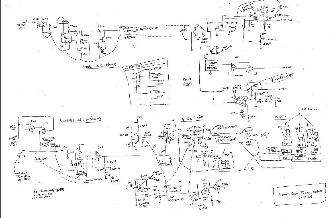
Jim Williams possessed a rare ability to combine his diverse talents in science, art, invention, and engineering. He created easily comprehensible tutorials, application notes, and technical phone conversations with customers, which facilitated improved designs in the field of electronics. Jim...
The power supply unit (PSU) in question does not appear to be exceptionally large. Eagle software should be capable of managing these dimensions. The focus was more on finding an alternative that may already include the necessary components and...
The April 1955 issue of Popular Electronics magazine features a cover illustration of a gentleman playing a homebuilt Theremin. Theremins are among the earliest electronic musical instruments, invented in the 1920s by Russian inventor Leon Theremin. The instrument is...