
Electronics and Home Automation

The circuit design described is a versatile and efficient solution for implementing IR remote control functionality. The architecture allows for multiple devices to communicate through a shared bus, which is particularly beneficial in complex systems where numerous remote-controlled devices are required. The active-low data line ensures that devices only respond when necessary, conserving power and reducing interference.
The choice of the Temic TSOP 1838 module as the initial prototype highlights the importance of selecting components that balance performance with availability. Although the module is discontinued, the recommendation of the Sharp IS1U60 as a viable alternative demonstrates adaptability in component sourcing. The specifications of the TSOP1838, including its power consumption and effective range, provide a solid foundation for understanding the circuit's capabilities.
The design's tolerance for modulation frequency variations emphasizes its robustness in real-world applications. The ability to fine-tune the frequency using resistor R3 or a trimmer allows for optimization based on specific environmental conditions and device requirements. This feature is crucial for maintaining reliable communication in varying lighting conditions, especially under fluorescent lights that can interfere with IR signals.
The transmitter design, which utilizes a transistor to drive the IR LED, showcases a practical approach to achieving desired output levels. The guidelines for resistor selection and power ratings ensure that the circuit operates safely and efficiently, while the option to bypass the transistor for short-range applications adds flexibility for different use cases.
Ultimately, this circuit serves as a foundation for further exploration and experimentation in IR communication systems. The encouragement for feedback and shared experiences fosters a collaborative environment for builders, enhancing the overall knowledge base and improving future iterations of the design.This is based on a circuit from the superb electronics info pages at. If you want to know more about IR remote controls, from circuit details to data protocols, look there for info (under `remote control`)! This design allows multiple transmitters and receivers, all connected to a common 2-pin bus, consisting of data and ground.
Data is active-l ow, pulled up by a resistor (in the transmitters) when not in use. This system was prototyped using the Temic TSOP 1838 module, then available from Maplin in the UK, which has now been discontinued. Keith Doxey may be able to sell you some. If anyone comes across another source for it, please let me know- contact details below. In the meantime, the Sharp IS1U60, available from RS Components, may do the same job (I`ve not yet tried it).
For reference, the Temic part draws 1mA, has a usable range of at least 6m indoors, and 1-2m under bright fluorescent light, and includes a 100k pullup resistor on the output. The TSOP1838 device is a complete IR receiver in a 3-pin package. All that is required is a 5V power supply, applied to the appropriate pins. In the near future, I will add a schematic for a simple supply derived from a 12V supply (eg a battery or a `wall-wart` type supply) Most equipment is quite tolerant of modulation frequencies varying by about 5% (eg 38kHz nominal, 36-40kHz will work), but if you have an oscilloscope or frequency meter, you can change R3 to get the output closer to 38kHz (capacitor tolerances are high, so the circuit as built could oscillate at 38kHz +/- 20%, reducing range).
If you don`t have access to any test equipment, and you need maximum range, fit a 200K trimmer in place of R3 and adjust it by trial and error for best results. This circuit is distributed as `feedbackware`- if you build it, let me know how you get on, and any helpful hints or modifications that might be useful to other constructors.
Thanks to those who have built the circuit already, and noticed problems or made suggestions- your contribution is appreciated. Note that this circuit transmits demodulated data between receivers and transmitters, so if your remote control uses an odd frequency (outside the typical 36-40kHz), you`ll need to modify things appropriately at the receiver (use a receiver which detects the appropriate modulation frequency) and transmitter (change the components to get the right modulation frequency, see NE555 data sheets for details).
There`s no reason why you can`t have your modified system coexisting on the same bus as other `normal` transmitters and receivers. This transmitter produces a 38kHz stream from the IR LED (D2), when the input pin is pulled low. Transistor T2 drives the LED at a reasonable current. Typically voltage drop across an IR LED is 1. 5V, so the resistor needs to drop about 10V, at about 0. 1A. Most IR LEDs can take more power than that at low duty cycles, so you might be able to use a bigger transistor and a smaller resistor to drive up to 1A peak through the LED if you really need long range.
The 100 ohm resistor should be a 0. 5W type, or better. Conversely, if you only need short range (by positioning transmitters within a metre of the devices being controlled), you may be able to dispense with the transistor, driving the LED directly from the timer output. Typical maximum drive current for a 7555 timer is 100mA, so play it safe and use a 200 ohm or larger resistor (1/4W should be adequate).
If you have acess to a spare pair of wires in your security system`s PIR detectors, IR receivers can be mounted in the detector, if not, have a look at the info on my retro-wiring page for hints on running cables. If this is the first electronic circuit you have built, some of the above information may seem like gibberish.
Several other people who are building the system hope to document their hints tips and experiences on a web page, when it happens, the links will appear here! This page i 🔗 External reference
Related Circuits

This circuit is easily identifiable by three equal-value capacitors and two equal-value resistors connected to the base of the transistor. The output signal of a transistor in COMMON EMITTER mode is FALLING when the input signal is RISING, which...
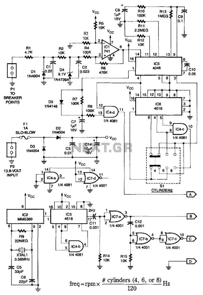
This system is compatible with 4-, 6-, or 8-cylinder automobiles. The timebase generated by IC5 functions as an oscillator that drives counter IC6, which divides the frequency by 6, 4, or 3 for 4-, 6-, or 8-cylinder engines, respectively....
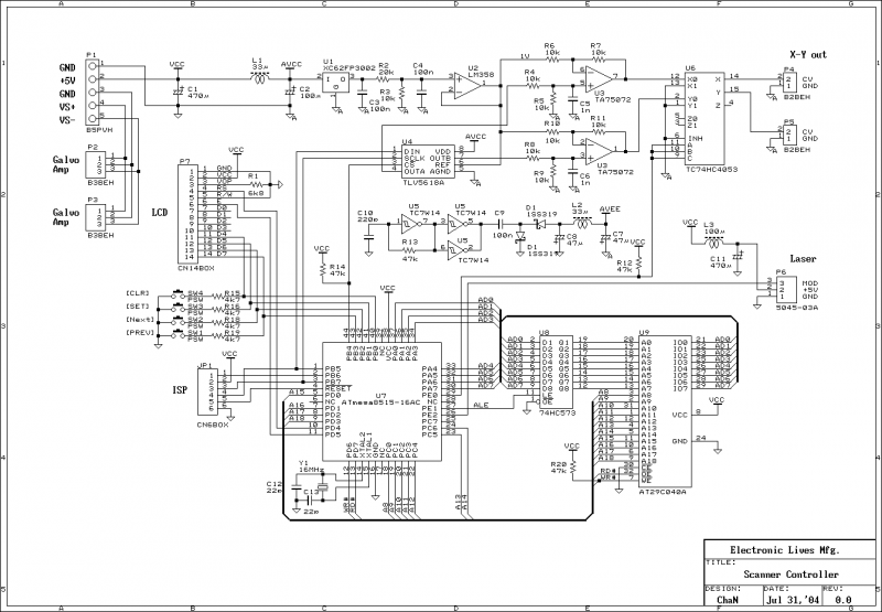
This document outlines the servo amplifier and its circuit diagram. It describes a straightforward operational amplifier circuit that integrates both a power amplifier and a small signal amplifier on the same board. Care must be taken to avoid unintended...
A clock utilizing numeric neon lamps, commonly referred to as nixies. These display devices were prevalent during the 1960s and 1970s, but their usage declined with the advent of LED displays. Today, nixies have become sought-after collectibles and are...
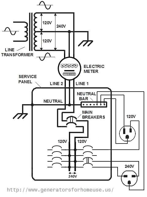
When considering a backup power system, adding an electric circuit, or installing a new appliance, it is crucial to understand the basics of home electrical wiring and the applicable codes. First, it is important to review how electricity reaches...
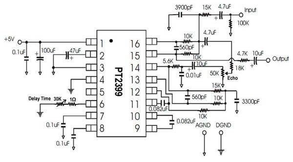
A single-chip circuit for echo and delay. If a microphone mixer circuit can be modified, this circuit can be easily used with a microphone. The PT2399 is an echo audio processor integrated circuit (IC) that utilizes CMOS technology and...