
electronic design software for large electronics

In the context of electronic design automation (EDA), the choice of software tools is critical for efficient workflow and effective circuit design. The Eagle software, known for its user-friendly interface and extensive component library, is particularly suitable for designing power supply units. The dimensions of the PSU under consideration suggest that Eagle can accommodate the required layout without issues.
When designing a PSU, it is essential to adhere to established conventions for schematic representation. This includes the correct depiction of components such as outlets, switches, and connectors, which can significantly impact the clarity and functionality of the design. The reference to the Schaffaur FN284 illustrates the importance of utilizing existing examples to guide the design process.
Moreover, the availability of component footprints is a crucial factor in the design process. While Eagle provides a wide range of footprints, it is acknowledged that no single software package can encompass every possible component. Therefore, engineers often need to develop their own libraries or enhance existing ones with additional parts they frequently encounter. This can include custom footprints for specific components or modifications of existing footprints to better fit the design requirements.
In conclusion, the effective use of Eagle software for PSU design relies on a combination of proper schematic conventions, the utilization of available resources, and the continuous expansion of personal component libraries. By maintaining an up-to-date library and leveraging the software's capabilities, designers can streamline their workflow and enhance the overall quality of their electronic designs.The PSU you`re referring to doesn`t look extraordinarily large to me.Eagle should be able to handle this kind of dimensions. I was more looking for something that may already have the components and be more suited for this kind of design (perhaps allow you to give wires colors, though I suppose with the Eagle labels we can type it out).
Also @stevenvh thank you for the edit. It isnt a size thing, it`s more that there are certain ways to draw these units, and the best way may be available in these programs. For example an outlet with a swtich that is present in the Schaffaur FN284 link. No schematic/layout package will have every component footprint you`ll ever need waiting for you. Part of doing electronics work is building up (or buying, or subscribing to) a footprint library consisting of all the parts you usually run across. Eagle has a lot of footprints, and there are plenty more freely available on their site, but it`s not complete by any means.
I usually end up adding a dozen or so parts to my library each year. 🔗 External reference
Related Circuits
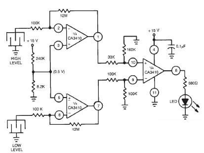
This liquid level sensor electronic circuit diagram utilizes a common CA3410 operational amplifier integrated circuit (IC). The sensor employs two plate sensors (or probes), one designated for detecting high liquid levels and the other for low liquid levels. If...
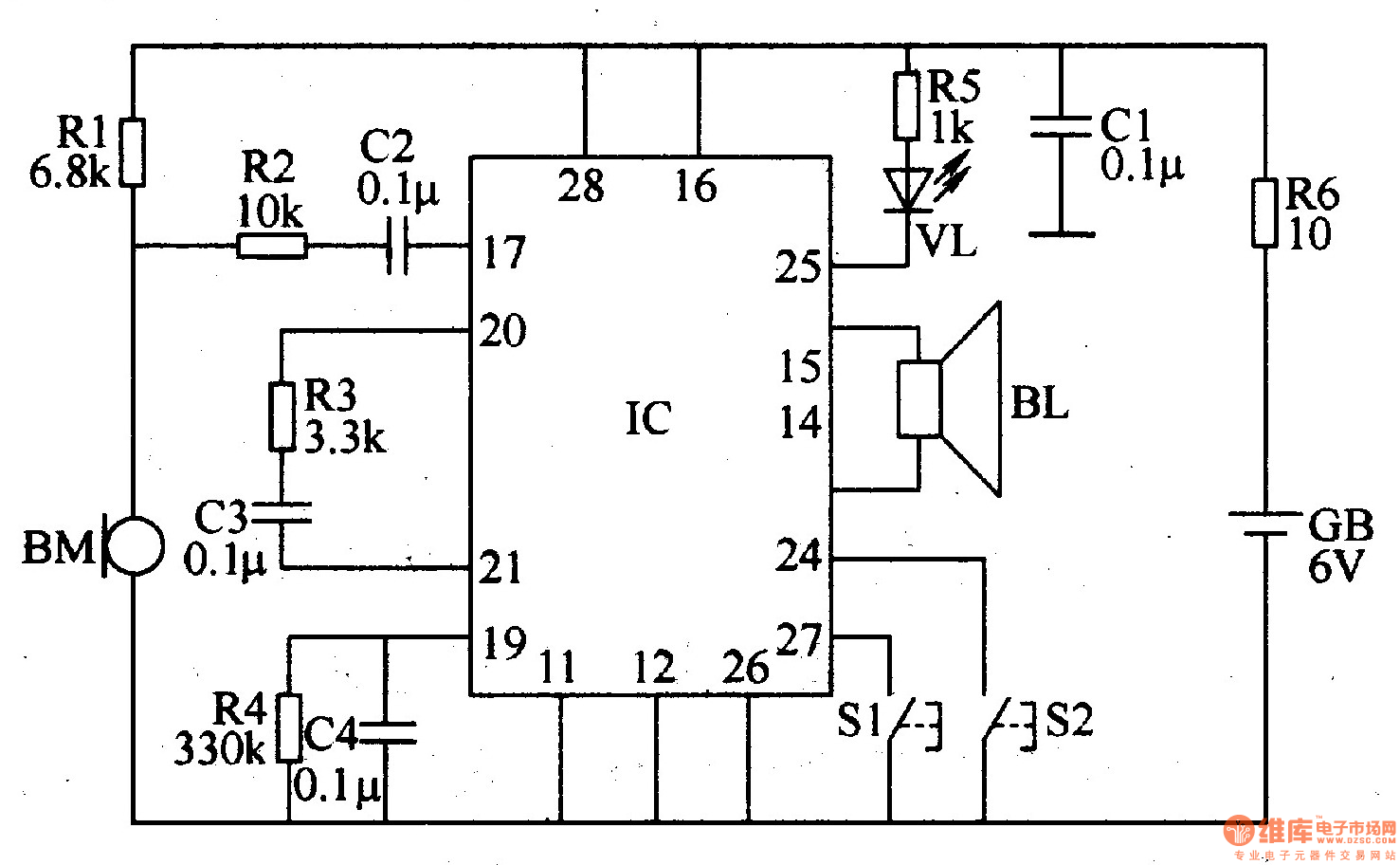
The recordable electronic doorbell consists of a recording and playback integrated circuit (IC), resistors R1-R6, capacitors C1-C4, a microphone (BM), a speaker (BL), control buttons S1 and S2, a battery (GB), and an LED (VL). Resistors R1-R5 should be...
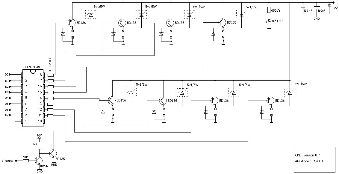
This project involves an output port expander for the 8051 microcontroller. It focuses on interfacing a large load bank with the microcontroller. In this load bank project, up to 50 solid-state relays are connected to the microcontroller using the...
Select a free schematic drawing software that resembles the two mentioned. There have been discussions regarding circuit drawing software. Fritzing is favored, although it lacks certain components, such as the RS232 component. There is a request for feedback on...
This article is about a software controlled, parallel port-interfacing 8-channel Pulse-Width-Modulated fan controller. I'll admit that the electronic part of it isn't very advanced, but hopefully the idea of "interfacing" might be interesting. My old partner and I were working...
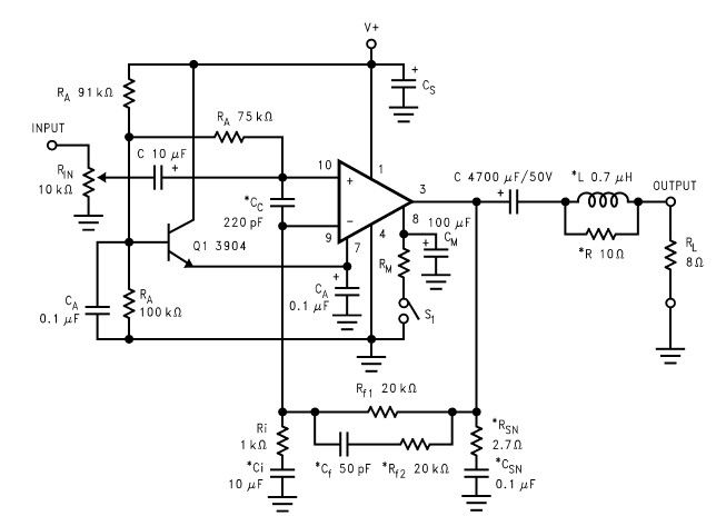
The LM2876 audio power amplifier circuit can be designed as a simple, high-efficiency audio amplifier capable of delivering 40W of continuous average power to an 8-ohm load with a total harmonic distortion plus noise (THD+N) of 0.1% from 20Hz...