
Beginning Embedded Electronics - 2

The circuit schematic involves several key components and connections that facilitate the operation of the ATmega328 microcontroller on a breadboard. The power supply for the circuit is managed through a voltage regulator that steps down the input voltage to a stable 5V, which is essential for the microcontroller's operation. The connection to the 5V rail is critical; it should be ensured that the voltage regulator's output is connected to the correct rail, providing power to the ATmega328.
The ATmega328 microcontroller is housed in a DIP package and requires careful placement on the breadboard to ensure proper pin alignment. The bending of the pins should be done gently to avoid damage. Each pin serves a specific function, with VCC pins connected to the 5V rail and GND pins connected to the ground rail. The RESET pin must be configured correctly to allow for a reset function, which can be achieved by connecting it directly to VCC or through a resistor for added control with a momentary switch.
Incorporating a tactile switch for the reset function enhances the usability of the circuit. The schematic should clearly illustrate the connections between the microcontroller, the voltage regulator, and the reset switch, ensuring that all components are correctly oriented and connected. The use of a multimeter with a continuity setting during assembly can assist in verifying connections and ensuring that the circuit is functioning as intended. Proper documentation of the pin configuration and connections will aid in troubleshooting and facilitate a better understanding of the circuit's operation.Get all the parts for this lecture here. We also highly recommend that you get a multimeter with a `continuity` setting. A good quality multimeter with this setting goes for ~$60 and as high as $300 for a really spectacular one. We like our $60 cheapo. Sorry for the confusion. When these tutorials were written and photographed, we used th e ATmega8. We now carry the newer ATmega328. You will find all ATmega328 information in the following pages, but the pictures will show an ATmega8. You will need to slightly bend in the legs of the DIP (dual inline package) to get the ATmega to straddle the breadboard center.
Be careful! Do not bend the pins too far inward. The pins of the ATmega should insert into the inner two most rows on the breadboard. I find it best to to insert one side and then slightly push the IC sideways until the other side of pins can insert into the opposite row on the breadboard. Confusing, I know. Note: The 5V `rail` is the horizontal row of holes next to the red line. You should have a wire connecting your 5V power regulator circuit to one hole on the 5V rail. This will energize all the holes next to the red line with 5V. This is true about the blue line as well. All the horizontal holes next to the blue line are connected together. One of these holes should be connected to the ground pin on your voltage regulator, and to the ground connection of your wall wart.
You can connect the VCC pins on the ATmega328 to any holes along the 5V rail, and you connect the GND pins on the ATmega328 to any hole along the blue GND rail. Oh, hey! If no one ever told you, there is a really simple way to figure out where pin 1 is on an IC. The manufacturer of anything polarized (tantalum caps, electrolytic caps, LEDs, ICs, etc) will always put some sort of marking on the device to indicate the how the device is supposed to be oriented.
For ICs, there is a small dimple on one end of the IC. The blue arrow in the picture is pointing to this dimple. The orange arrow points at pin 1, and the blue labels show how the pin numbers increase. Counting from the dimple, pin 1 is on the left and increases down the left side of the IC. The pin numbers jump to the right side row of pins and count up. See image from the ATmega328 datasheet below. The ATmega328 should be in the breadboard, pin 7 (VCC) and pin 20 (AVCC) should be connected to your 5V rail and pins 8 and 22 (GND) should be connected to GND on your bread board. If you turn your power circuit on, the ATmega328 is now running, but it has nothing to run! Actually this is not wholly true - there is one more connection that needs to be made before the ATmega328 starts running code.
The RESET pin on the ATmega328 needs to be connected to VCC. You can either wire the RESET pin directly to 5V or you can `tie it high` by connecting the RESET pin to VCC through a resistor. This will allow you to add a momentary reset button. What`s this The reset line on the ATmega328 is exactly what it sounds like - it resets the micro just like the reset works on your computer.
If you look at the ATmega328 datasheet you`ll see the RESET label is written with a line above it. This is nomenclature that indicates the reset pin is active low. What is `active low` The RESET pin is an input. A low level on this pin will put the micro into reset - i. e. the pin is activated with a low input, aka `active low`. So unless you want your ATmega328 to stay in reset, you`ll need to pull this pin high. Now you need a reset button. A momentary switch is a switch that is activated (or closed) while you`re touching it and open when you release the button. These are often called `tactile switches` because they `click` when you depress them giving the person pressing the button some `tactile` feedback.
This is what the schematic part looks like. Notice pins 1 and 2 are connected together. 3 and 4 are connected together. And when you press `de button, it t 🔗 External reference
Related Circuits
The following is an account of such an undertaking. Recently, a design review was conducted for a cost reduction project where an older design was updated. The new design merged two different designs, incorporating some updated components alongside existing...
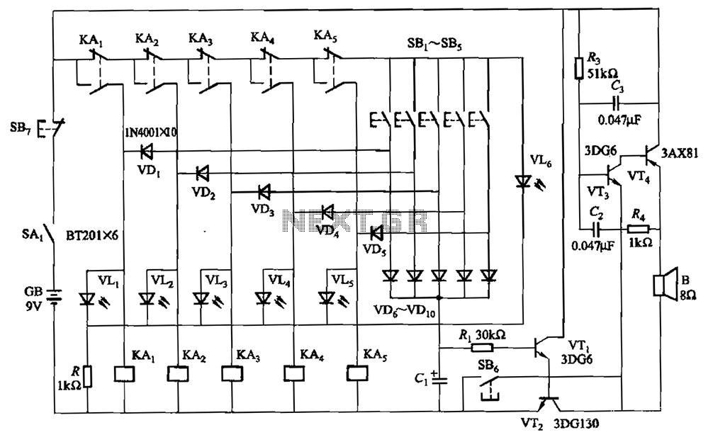
A relay-style circuit designed for a five electronic responder group. This circuit features self-locking capabilities, sound and light displays, time monitoring, and additional functions. The circuit includes a monitoring time button operated by the moderator. When this button is...
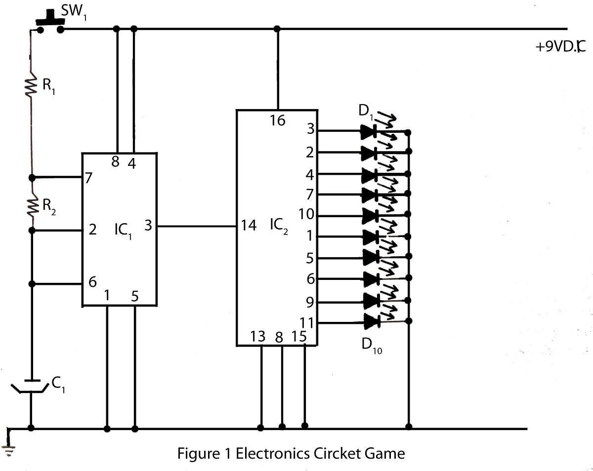
The electronics cricket game circuit presented on this website is a straightforward and easy-to-build circuit diagram for an electronics cricket project, as well as various other game projects. The electronics cricket game circuit typically consists of several key components that...
Fixed some issues with the Benito Arduino programmer and upgraded it to the latest version of the LUFA library. There was a mismatch between the INF file and the library-supplied descriptors. Apologies to the two XP users. As this...
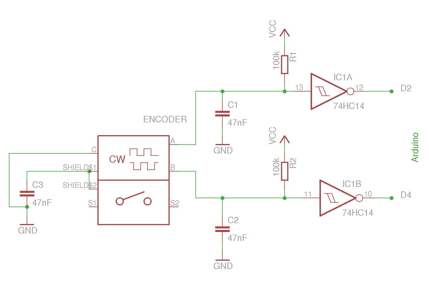
The example circuit and code should be sufficient to begin without delving into additional details. A rotary encoder is an electromechanical component with a shaft that records rotation and converts it into electrical pulses to indicate the direction of...
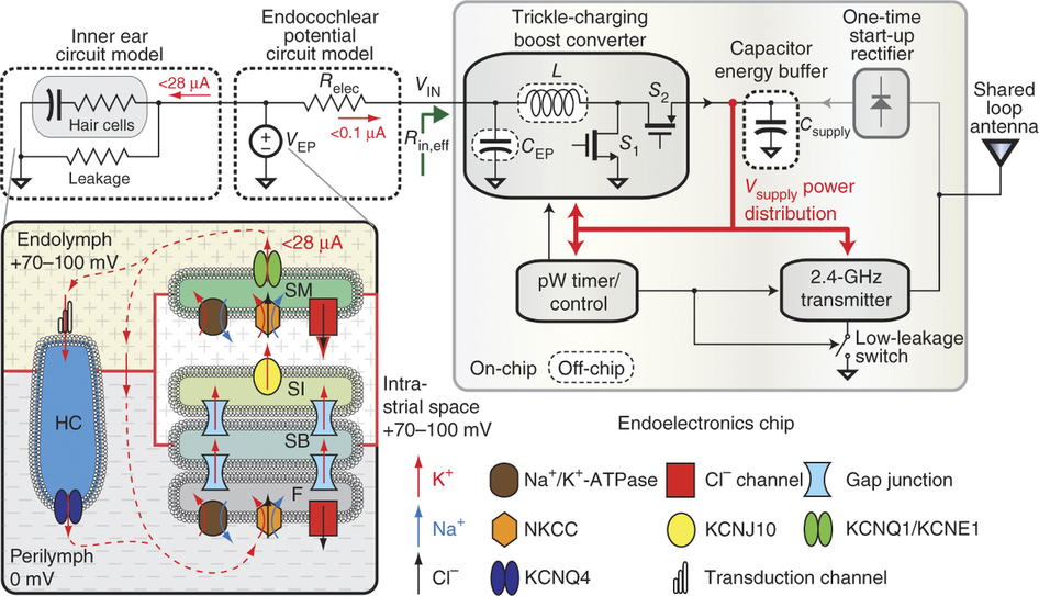
To generate and maintain the endocochlear potential (EP), perilymphatic potassium ions (K+) enter fibrocytes (F) through the Na+/K+-ATPase and Na-K-Cl cotransporter. Gap junction networks connect fibrocytes to strial basal (SB) and intermediate (SI) cells, allowing ions to enter the...