
Electronics - circuit relay type answer
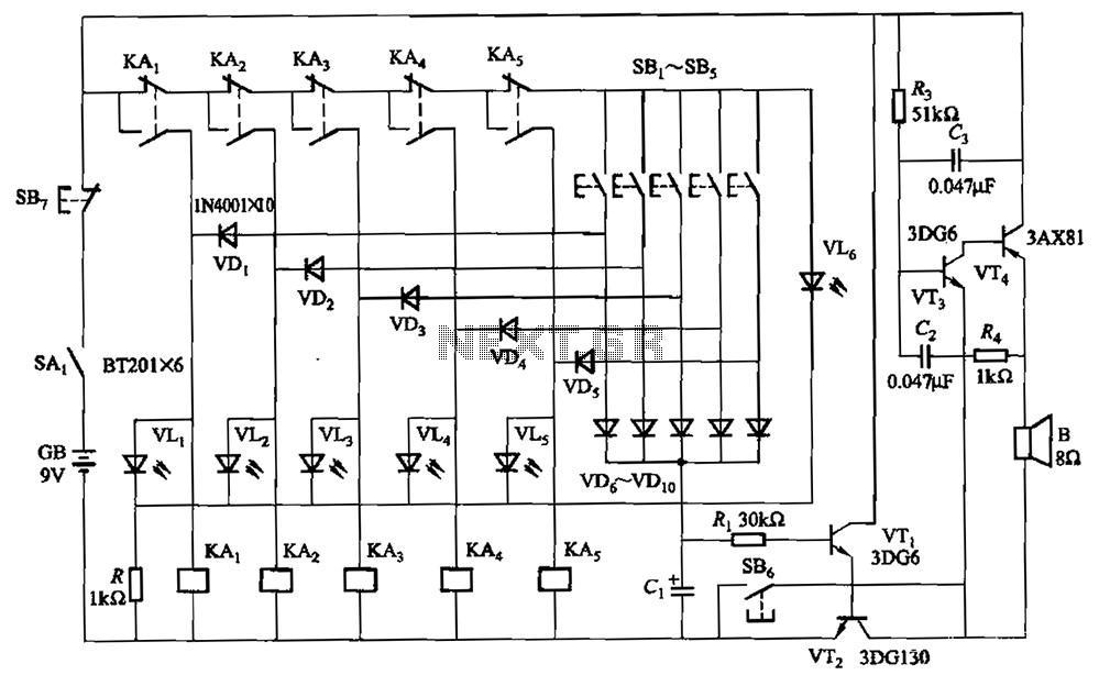
The relay-style five electronic responder group circuit is engineered to facilitate interactive sessions where participants respond to questions. The core of the circuit consists of five responder units, each equipped with a relay that activates upon receiving a signal. This setup allows for simultaneous participation from multiple users, enhancing the engagement of the event.
The self-locking feature ensures that once a participant has activated their responder, it remains engaged until it is intentionally reset, preventing accidental multiple submissions. The sound and light display serves as an effective means of communication, providing visual and auditory cues to participants regarding the status of their responses.
The monitoring time button, operated by the moderator, plays a crucial role in managing the flow of the session. When activated, an audio announcement is made, clearly indicating to all participants that the time for submitting responses is over. This feature is vital in maintaining order and ensuring that all participants adhere to the time constraints.
The SB7 button is strategically integrated into the circuit to allow the host to manage the session effectively. When a question has been thoroughly answered or when the time limit has been reached, the host can press this button to reset the circuit. This action prepares the system for the next question or round, ensuring a seamless transition and maintaining engagement throughout the session.
Overall, the design of this relay-style responder circuit is aimed at enhancing interactive experiences, providing clear communication, and ensuring effective time management during events. The combination of self-locking mechanisms, audio cues, and host control buttons contributes to a well-organized and efficient response system.A relay-style five electronic Responder Responder group circuit. The circuit has a self-locking, sound and light display, monitor time and other functions. Large ones may be in creased. Drawing, buttons SBe is monitoring time button by the moderator master. Press this button, audio circuit voice, told Time has come to stop writing ; button SB7 role is when the question answered, or because of the time to stop to answer, the host press the button briefly, the circuit recovery.
Related Circuits
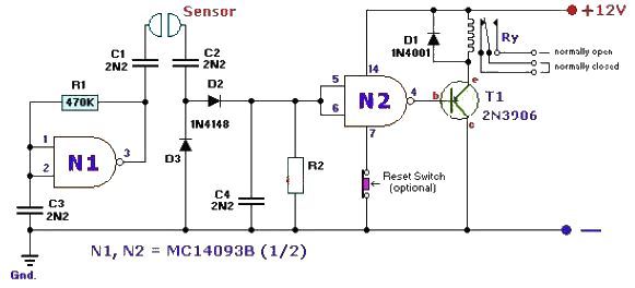
This fluid level sensor circuit is designed to use an AC sensing signal to prevent electrolytic corrosion on the probes. The rectified AC signal is utilized to drive a T1 transistor, which in turn activates a 12-volt relay that...
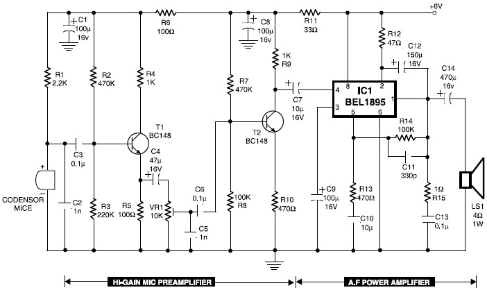
Transistors T1 and T2 form the microphone preamplifier. Resistor R1 provides the necessary bias for the microphone condenser, while preset VR1 functions as a gain control to adjust the gain level. To enhance audio power, the low-level audio output...
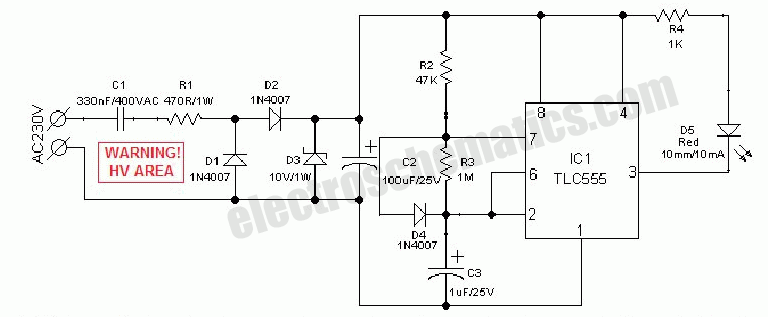
An AC mains operated single LED flasher circuit is constructed using the widely utilized CMOS timer chip TLC555. The entire circuit is powered directly from the 230VAC grid supply via a capacitive potential divider and associated components. This compact...
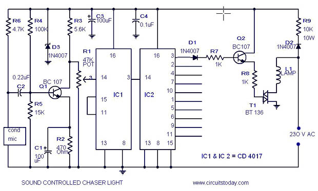
A simple musical light chaser circuit diagram and schematic using IC CD4016. This circuit blinks lights in response to sound, audio, or music output, causing 10 lights to dance according to sound frequency. The musical light chaser circuit utilizing the...
The circuit depicted can be utilized to control a unipolar stepper motor equipped with four coils. This design is derived from an older fax machine. The circuit is capable of handling a motor current of approximately 500 mA per...

An issue with CPLD and FPGA devices is that they have numerous I/O pins, resulting in schematics that quickly become overwhelmingly large. Different sections of the schematic have been partitioned to illustrate the motor control circuit, analog-to-digital converter circuit,...