
Bell Alarm

The described circuit integrates a motion sensor lamp with an acoustic signaling feature, enhancing outdoor lighting systems. The series connection of components allows for the controlled operation of the lamp while simultaneously generating an alert sound. The use of a bridge rectifier is crucial for converting AC mains voltage to a usable DC voltage for the circuit. The design ensures that the acoustic signal activates immediately upon lamp operation, providing instant feedback to the user.
Resistor R1 is a critical component, as it regulates the voltage drop necessary for the circuit's operation. The choice of R1's value directly affects the current flow and the resulting acoustic signal. In scenarios involving higher wattage lamps, careful consideration of R1's resistance is essential to prevent overheating and ensure reliable operation. Capacitor C1 plays a vital role in smoothing the output voltage, ensuring that fluctuations do not adversely affect the performance of the buzzer and the overall circuit functionality.
The bridge rectifier must be selected based on the expected load current, particularly for applications involving higher wattage lamps. The rectifier's specifications should accommodate the peak currents experienced during lamp activation. Furthermore, the heat dissipation properties of R1 necessitate adequate spacing and heat management strategies within the circuit layout to maintain optimal performance and longevity.
Overall, this circuit design exemplifies an innovative approach to integrating acoustic signaling with outdoor lighting, enhancing both functionality and user experience. Proper component selection, layout considerations, and adherence to safety protocols will ensure a successful implementation of this circuit in practical applications.If you use a lamp with a motion sensor for outdoor lighting, the original electrical switch is actually no longer necessary. If you replace the switch with the circuit described here, an acoustical signal will be generated each time the outdoor lamp is switched on.
It`s thus somewhere between an alarm and a doorbell. The operating principle is simple. A circuit that causes a voltage drop of only a couple of volts is connected in series with the lamp. As the circuit needs a DC voltage, the current for the lamp is passed through a bridge rectifier. The voltage drop across the circuit is determined by R1. The function of C1 is to smooth the raw DC voltage. Note that this is not an example of peak rectification, but instead of averaging. For this reason, the voltage on C1 is lower than you might expect. Ultimately, the DC voltage on C1 reaches the same value as the average voltage across R1. For example, consider what happens with a 100-W lamp. For convenience, we can assume that the lamp has a resistance of 529 R. If we ignore the voltage across the diodes and the voltage across R1, the current is approximately 0. 39 A on average (not 0. 43 A). This is because the average mains voltage is only 207 V = (230 G— v2) G· (p/2). This yields a voltage of approximately 8. 5 V on C1. As the buzzer and T1 only draw a few milliampG¨res from C1, in practice the voltage will differ from this value by at most a few tenths of a volt.
Here you should use a DC buzzer with a large operating voltage range. A good example is the CEP-2260A, which has a voltage range of 3 20 V (available from Digi-Key and other online sources). The charging time of C2 determines how long the buzzer remains energised, and here it will be a few tenths of a second.
Depending on how much current the buzzer draws, you can increase the value of R2 in order to extend the time (this is certainly necessary with the above-mentioned buzzer type). Depending on the lamp power, you can consider adjusting the value of R1. This will certainly be necessary if you use a 150-W lamp or larger. In this case, cut the value of R1 in half, primarily because the power dissipation will otherwise be too large.
In the example described here, it is around 3 watts. The bridge rectifier also deserves special attention. A large current can flow briefly when the lamp is switched on cold`. A 250V, 1. 5-A bridge rectifier is adequate for a 100-W lamp, but heavier-duty diodes are necessary with higher lamp power such as the 1N5408 (1000 V / 3 A). Due to the heat generated by R1, make sure that R1 is located a certain distance away from the other components in the assembled circuit.
Also bear in mind that the entire circuit is connected to mains potential. Never make any adjustments while the circuit is connected to the mains! It`s thus a good idea to test the circuit before fitting it into the switch box. 🔗 External reference
Related Circuits

This is a simple automatic light switch circuit designed for bedrooms. After construction, the input terminals of this circuit should be connected in parallel to the intended lighting fixture. The automatic light switch circuit utilizes a light-dependent resistor (LDR) as...

In some situations, a more complex approach is necessary, even when a simpler method is available. This scenario involves adding a second doorbell in parallel with an existing one. While this typically does not require additional electronic components, connecting...

The transmitter circuit is activated by pressing the SB button. Components D1, D2, R2, R3, and C4 form a low-frequency oscillator that controls an audio oscillator made up of D3, D4, D5, and D6, allowing them to operate alternately....
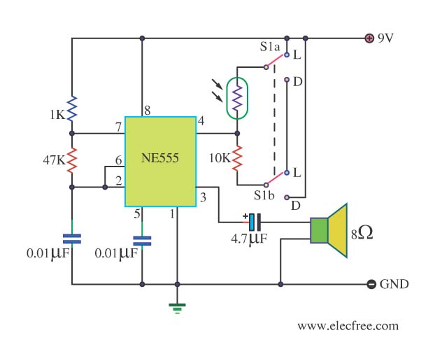
This circuit detects light and provides a voice warning. It responds to changes in light conditions, becoming active based on the position of switch S1. The circuit utilizes a light-dependent resistor (LDR) to sense ambient light levels. When the light...

The sensor must be positioned at an angle of approximately 30 to 45 degrees relative to the ground. This orientation facilitates the drainage of rainwater, preventing accumulation that could trigger the alarm due to water retention on the sensor....
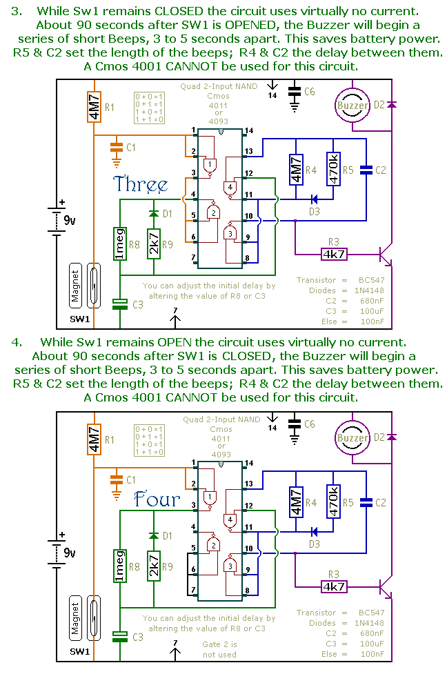
This document presents a collection of compact, self-contained alarm circuits. These circuits are designed to operate with a very low standby current, making them ideal for battery-powered applications. They can be triggered by both normally-open and normally-closed switches, while...