
Doorbell Cascade
The circuit design for adding a second doorbell in parallel involves several key components to ensure reliable operation while minimizing the load on the existing transformer. The primary components include a push-button switch, a bridge rectifier, a relay, and a secondary bell with its dedicated transformer.
1. **Push-Button Switch**: This component is the user interface for activating the second doorbell. When pressed, it sends a signal to the bridge rectifier.
2. **Bridge Rectifier**: The bridge rectifier consists of four diodes arranged in a configuration that allows it to convert the alternating current (AC) from the existing doorbell system into direct current (DC). This conversion is necessary for the relay to operate effectively.
3. **Relay**: The relay acts as an electronic switch that closes the circuit for the second bell when the push-button is pressed. It is rated to handle the power requirements of the second doorbell, ensuring that it can operate independently of the first bell's transformer.
4. **Secondary Bell and Transformer**: The second doorbell is connected to its own transformer, which is appropriately rated for its power needs. This setup prevents any overloading of the existing transformer and allows for the independent operation of both bells.
The overall circuit configuration ensures that the second doorbell can be activated without compromising the performance of the existing doorbell system. By using a bridge rectifier and relay, the circuit efficiently manages the power distribution, allowing for the addition of a second doorbell without the need for extensive modifications to the existing electrical setup. This approach not only simplifies installation but also provides a cost-effective solution for expanding doorbell functionality.Sometimes you have to do it the hard way, even if doing it the easy way is an option. That is the case here. The intention is to add a second doorbell in parallel with the existing bell. This does not, in principle, require any electronic components. You would simply connect the second bell to the first one. But if the existing bell transformer is not rated for the additional load then this is not a good idea! An option is to buy a new and larger transformer. But bigger also means more expensive! Moreover, replacing the existing transformer can be an awkward job, for example when it is built into the meter box. So we follow different approach. This circuit is connected in parallel with the existing bell. This is possible because the current consumption is very small compared to the load of the bell. The bridge rectifier rectifies the bell voltage when the push-button is pressed. This will then close therelay contacts. These contacts are the electronic` button for the second bell, which is powered from its own cheap bell transformer.
🔗 External reference
Related Circuits
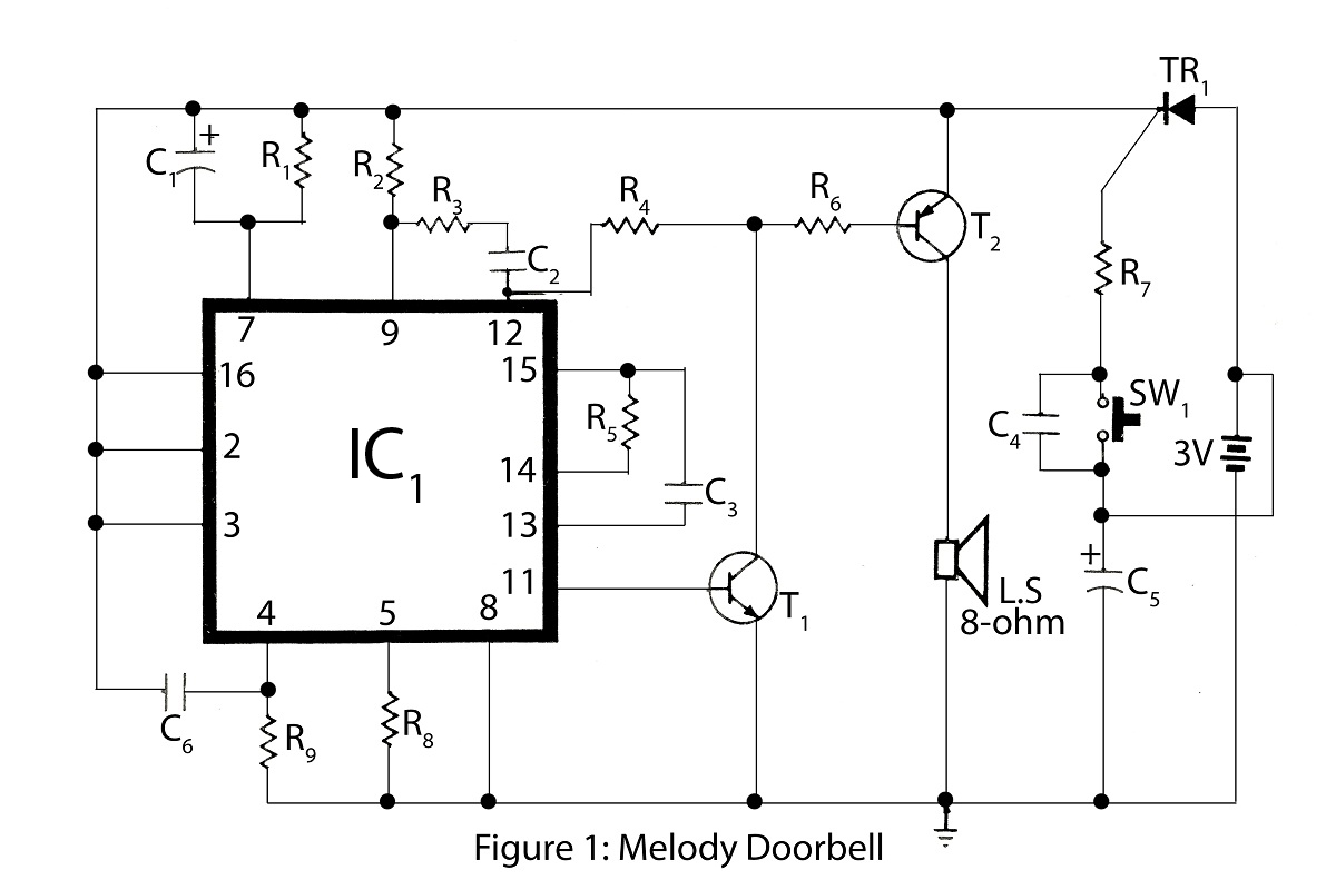
The Advanced Melody doorbell is an intriguing project within the series of alarm circuit diagrams. It features a melody doorbell that operates using a battery instead of AC mains power. The Advanced Melody doorbell circuit is designed to provide a...
Figure 15-22 illustrates a doorbell system that consists of a monostable timing circuit, a password switch, a NAND gate circuit, and a sound output circuit. The operation of the circuit is designed such that when the password switch is...
This circuit activates a lamp at a remote location when the doorbell switch is pressed. It is designed specifically for solenoid-type doorbells, as electronic doorbells that play tunes are incompatible. The circuit addresses the issue of potentially missing the...
Instructions for wiring and installing a doorbell in your home. The installation of a doorbell involves several key steps to ensure proper functionality and safety. The process typically begins with selecting the appropriate doorbell type, which can be either wired...
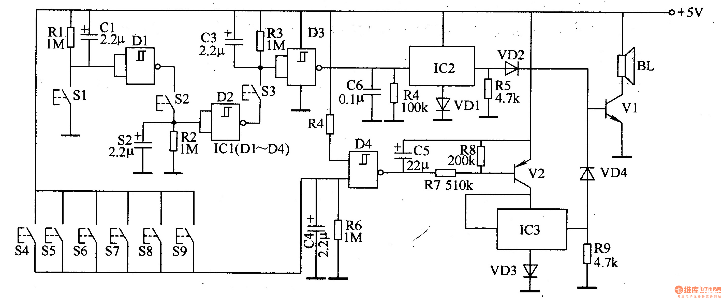
The password electronic doorbell circuit comprises a trigger circuit and a music generating circuit, as illustrated in Figure 3-119. The trigger circuit includes buttons S1-S9, four NAND gate Schmitt trigger integrated circuits (IC1), and external RC components. The music...
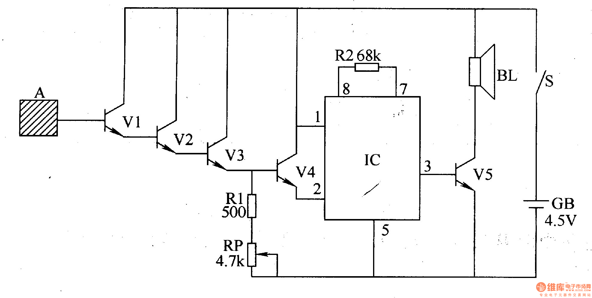
The inductive electronic doorbell circuit consists of an inductive electronic switch and a music generator circuit, as illustrated in Figure 3-115. The inductive electronic switch circuit includes an inductive electrode A, transistors V1-V4, a resistor R1, and a potentiometer...