
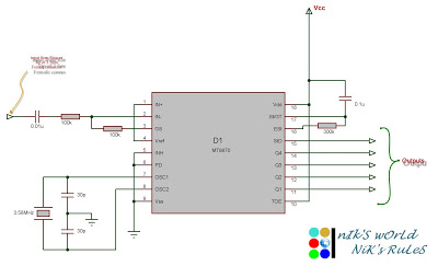
Bells Ring Generator Circuit Schematic
The circuit operates using a combination of integrated circuits and transistors to produce a dual-tone sound effect. The central components include two frequency generators (IC1D and IC1F) that create distinct audio frequencies corresponding to the "Ding" and "Dong" sounds. The transistors Q2 and Q5 serve to shape these waveforms, manipulating their amplitude and decay characteristics to emulate the natural ringing of bells. The mixed output from these transistors is then processed through resistors R7 and R13, which work to blend the two tones harmoniously.
The filtering component, C5, is crucial for smoothing the output signal, ensuring that the sound produced is pleasant and bell-like without harsh artifacts. The class-A audio amplifier, constructed from Q3 and Q4, provides sufficient power to drive a loudspeaker, allowing the tones to be heard clearly. The activation of this amplifier is controlled by Q1, which engages the amplifier circuit when P1 is pressed, ensuring that the sound is produced only when desired.
The time-delay feature, managed by C1 and R2, allows the circuit to enter a low-power standby mode after the button is released, making it energy efficient. Modifications to achieve the "Ding-Dong" functionality involve careful removal of D4 and the adjustment of C10 and R15 to establish the desired timing between the two tones.
In applications where a photo-resistor is utilized, the circuit can respond to ambient light changes, providing an innovative way to integrate sound with visual elements, such as the seasonal lighting of a Christmas tree. Finally, for those seeking enhanced audio output, substituting the existing components with an integrated audio amplifier like the LM386 or LM380 can significantly improve sound levels, provided the power supply is appropriately increased and other components are adjusted to maintain the correct tone frequencies. This flexibility makes the circuit suitable for a wide range of applications beyond simple doorbell functions.This circuit generates a dual-tone bells ringing similar to most door-bell units. It can be used in many applications other than door-bell. In the Notes below several options will be given in order to suit different needs. The circuit as shown in the diagram generates a "Ding-tone" when P1 is pressed and a "Dong-tone" when P1 is released. IC1D is the first-tone frequency generator and IC1F generates the second-tone. Q2, Q5 and related components act as shape and decay controls of the two tones, trying to imitate as close as possible the bells sound. Their outputs are mixed (R7 & R13), filtered (C5) and boosted by a simple class-A audio amplifier (Q3 & Q4) in order to drive the loudspeaker.
The amplifier is switched-on by Q1 when P1 is pressed, then is switched-off some seconds after P1 is released: this time-delay is fixed by C1 & R2. In this way the circuit will draw a negligible current when in stand-by mode. To obtain a "Ding-Dong" operation when pushing on P1, no matter when it is released, you must modify the circuit as shown in the frame placed at the low-right corner of the circuit diagram.
D4 must be removed. C10 & R15 set the time-delay separating first and second tone. An amusing application of this circuit wired as in the original schematic, is to use a photo-resistor in place of P1, then placing the unit near the flashing lamps of your Christmas tree. A soft bell sound may be heard at switch-on and switch-off of the lamp chosen. To obtain higher output power you may substitute R8, Q3 & Q4 with an audio amplifier IC like the LM386 or LM380.
In this case power supply must be raised to 6 - 12V but at the same time R4 & R10 should be changed to adjust bell-tone frequencies. 🔗 External reference
Related Circuits

The utility vehicle anti-theft alarm circuit consists primarily of two main components essential for its operation. The security circuit is activated when the vehicle owner departs from the vehicle, utilizing an anti-theft switch (S B) to engage the alarm...
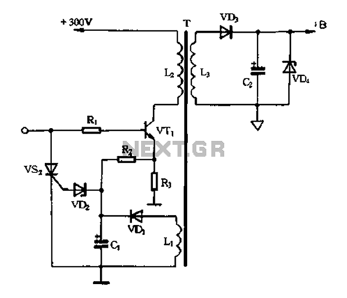
Color TV main power protection circuit The color TV main power protection circuit is designed to safeguard the television's power supply from various electrical anomalies, such as overvoltage, undervoltage, and short circuits. This circuit typically employs several components, including fuses,...
Connect the serial cable to the serial port. If using a USB to TTL, RS232, or serial converter, plug it into the USB port. Next, short the Tx pin to the Rx pin or the TxD pin to the...
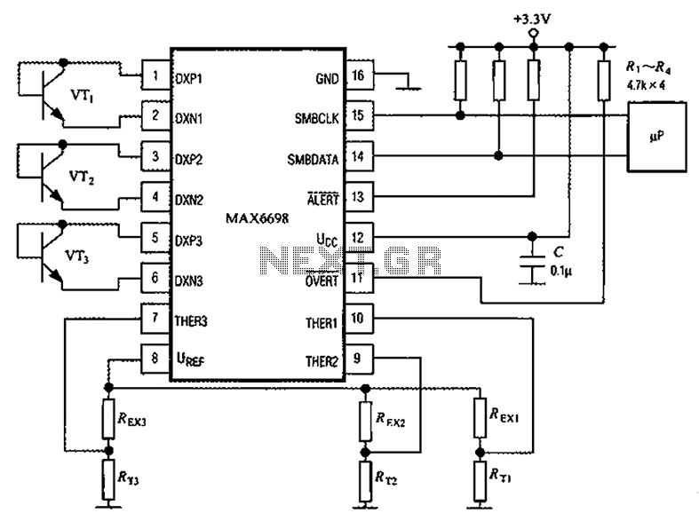
Channel 7 presents a circuit diagram of a smart temperature sensor using the MAX6698. This circuit includes three transistors (VT1, VT2, and VT3) and three thermistors (RT1, RT2, and RT3). An internal reference voltage source is provided via resistors...
The wireless FM transmitter circuit described here includes an additional RF power amplifier stage following the oscillator stage, which increases the power output to 200-250 mW. The wireless FM transmitter circuit functions by modulating audio signals onto a radio frequency...
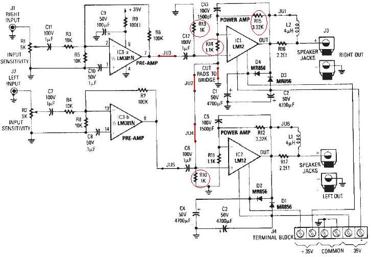
The LM12 audio amplifier circuit is designed to deliver high output power for loads with impedances of 4 ohms or 8 ohms. The maximum output power achievable by this amplifier is approximately 60 watts for a 4-ohm load and...
Warning: include(partials/cookie-banner.php): Failed to open stream: Permission denied in /var/www/html/nextgr/view-circuit.php on line 713
Warning: include(): Failed opening 'partials/cookie-banner.php' for inclusion (include_path='.:/usr/share/php') in /var/www/html/nextgr/view-circuit.php on line 713