
Simple Car theft alarm system circuit using NE555

The utility vehicle anti-theft alarm circuit is designed to enhance the security of vehicles by deterring theft through an audible alarm system. The circuit is fundamentally divided into two key sections: the detection mechanism and the alarm activation system.
The detection mechanism is initiated when the vehicle owner exits the vehicle and activates the anti-theft switch (S B). This switch is typically a normally open contact that closes when engaged, signaling the system to monitor for unauthorized access. If an intrusion is detected, the system triggers the alarm.
The alarm activation system is responsible for generating a loud sound to alert nearby individuals of the potential theft. This may include a piezoelectric buzzer or horn, which is powered by the vehicle's battery. The alarm circuit can be designed to include additional features such as a time delay to prevent false alarms caused by environmental factors, or a flashing LED indicator that visually signals the alarm status.
To ensure reliability, the circuit may also incorporate a backup power source, such as a capacitor or a small battery, which allows the alarm to function even if the vehicle's main battery is disconnected or depleted. Furthermore, the design can include additional sensors, such as door switches or motion detectors, to enhance the security coverage of the vehicle.
Overall, the utility vehicle anti-theft alarm circuit is a crucial component in vehicle security systems, providing peace of mind to vehicle owners through its effective monitoring and alerting capabilities.Utility vehicle anti-theft alarm circuit as shown. It is mainly composed of two major anti-theft alarm circuit parts and components. Security circuit: When the car owner left the car, it will be placed on anti-theft switch S B, and make the.. 🔗 External reference
Related Circuits
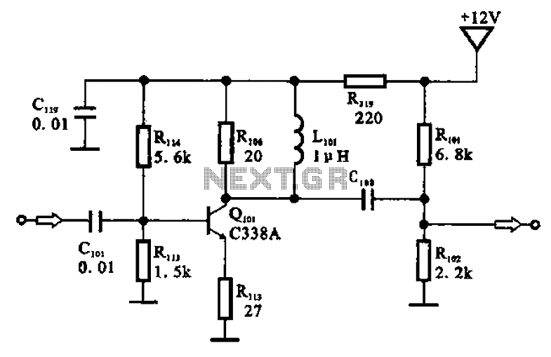
The amplifier circuit is designed as a pre-amplifier configuration. It utilizes transistor Q101 and other components such as inductor L101 and biasing elements. The transistor operates as a common emitter intermediate frequency (IF) amplifier. The IF signal is coupled...
The standard Class AB audio power amplifier allows for direct coupling of the amplifier's output to speakers. This is beneficial as it eliminates capacitors or transformers that could compromise sound quality. The speakers are connected directly to the amplifying...
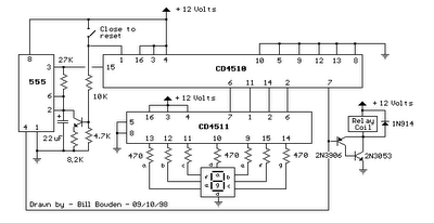
When the switch is opened, the timer generates an approximate 1-second clock signal, decrementing the counter until it reaches a count of zero. Upon reaching zero, the carry-out signal at pin 7 of the counter goes low, energizing a...
When the ON/OFF button is pressed once, the equipment goes on and stays on. It goes off when the button is pressed again. The circuit is straightforward. It uses a JK CMOS Flip-Flop with its JK terminals tied high...
The monostable 555 timer multivibrator circuit, also known as a one-shot monostable multivibrator, functions as a retriggerable pulse generator. The term "monostable" indicates that the circuit has only one stable state, with the unstable state referred to as the...

The SA607 is a low voltage, high-performance monolithic FM intermediate frequency (IF) system that includes a mixer, oscillator, two limiting intermediate frequency amplifiers, a quadrature detector, a logarithmic received signal strength indicator (RSSI), a voltage regulator, and audio and...
Warning: include(partials/cookie-banner.php): Failed to open stream: Permission denied in /var/www/html/nextgr/view-circuit.php on line 713
Warning: include(): Failed opening 'partials/cookie-banner.php' for inclusion (include_path='.:/usr/share/php') in /var/www/html/nextgr/view-circuit.php on line 713