
With a 7-Channel Smart Temperature Sensor MAX6698 circuit diagram
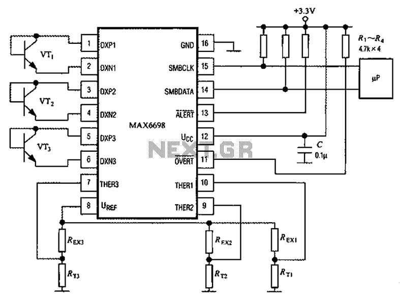
The circuit configuration of the MAX6698 smart temperature sensor is designed to monitor temperature variations accurately through the use of thermistors, which are temperature-sensitive resistors. The three thermistors (RT1, RT2, RT3) are strategically placed to measure different temperature points, allowing for a comprehensive assessment of environmental conditions. Each thermistor's resistance changes with temperature, producing a corresponding voltage drop that is read by the MAX6698.
The transistors (VT1, VT2, VT3) serve as amplifiers or switches in the circuit, enhancing the signal received from the thermistors. The choice of transistors, such as CMPT3904, SST3904, KST3904-TF, SMBT3904, and FMMT3904CT-ND, provides flexibility in terms of performance characteristics, including gain and frequency response, which can be critical depending on the specific application.
The internal reference voltage source, created by the resistors UREF REX1, REX2, and REX3, ensures that the thermistors are powered adequately and consistently. This stable power supply is crucial for accurate temperature readings, as fluctuations in voltage can lead to erroneous measurements.
Overall, the MAX6698 circuit diagram illustrates a sophisticated approach to temperature sensing, integrating multiple components to achieve precise and reliable performance in various applications, from industrial monitoring to consumer electronics. The design's modular nature allows for easy adjustments and scalability, making it suitable for a wide range of temperature sensing needs. Channel 7 has a circuit diagram of a smart temperature sensor MAX6698 is shown in Figure: MAX6698 maximum temperature with three transistors (VT1 ~ VT3) and three thermistors ( RT1 ~ RT3). The internal reference voltage source via a resistor UREF REX1 ~ REX3 were given three thermistor power supply, the voltage drop across the thermistor respectively supplied THER1 ~ THER3 pins. Temperature transistor can be used CMPT3904, SST3904, KST3904-TF, SMBT3904, FMMT3904CT-ND models.
Related Circuits
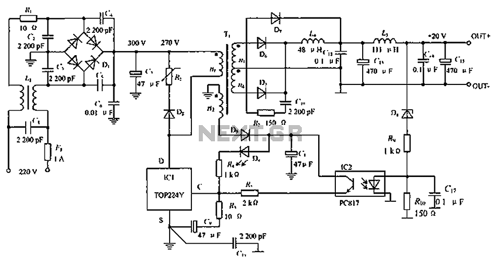
The circuit depicted in the figure is designed to achieve a higher power output by modifying specific components. On the left side of the figure, components R1, L1, D1, and capacitors C1 to C7 form a conventional filtering and...
Figure 2-32 (a) illustrates the time control diagram for a motor operated by switch S1. When S1 is set to position 1, the power driver circuit supplies current to the motor, enabling it to run. When S1 is switched...
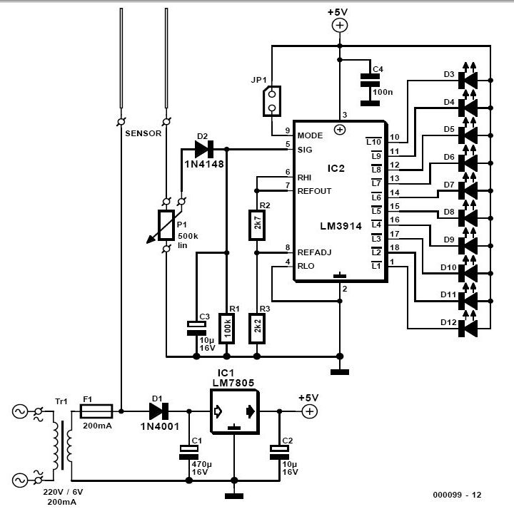
For individuals who prefer not to engage directly with soil, this simple soil moisture tester efficiently assesses the condition of their plants and the level of care they require. The soil moisture tester is a device designed to measure the...

A simple touch dimmer circuit diagram using the TT6061 IC, which is a touch control integrated circuit used for light dimmer circuits and lamp dimmer circuits. The touch dimmer circuit utilizing the TT6061 IC is designed to provide a user-friendly...
D1, D2, C1, and C2 double the AC input voltage, charging capacitor C3 through resistor R1 to approximately 320 volts. Resistor R1 isolates the voltage doubler from the discharge capacitor C3, ensuring that capacitors C1 and C2 do not...
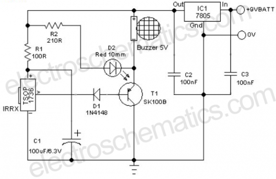
A remote-controlled alarm circuit utilizing the TSOP1736. This circuit involves routing an electric cable to connect a calling bell switch near the bed of an elderly individual. The remote-controlled alarm circuit designed with the TSOP1736 is an innovative solution for...
Warning: include(partials/cookie-banner.php): Failed to open stream: Permission denied in /var/www/html/nextgr/view-circuit.php on line 713
Warning: include(): Failed opening 'partials/cookie-banner.php' for inclusion (include_path='.:/usr/share/php') in /var/www/html/nextgr/view-circuit.php on line 713