
BENCHTOP FUNCTION GENERATOR WITH BUILT IN COUNTER
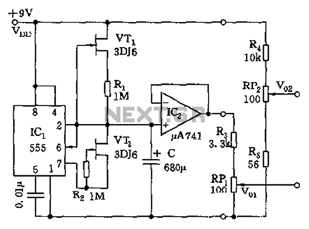
The circuit utilizes a function generator IC capable of producing various waveform outputs, such as sine, square, and triangle waves. The frequency range is achieved through a combination of resistors and capacitors that determine the timing characteristics of the output waveforms. The output stage may include an operational amplifier to buffer the signal and ensure that the waveform maintains its integrity across the specified frequency range.
A CMOS counter is integrated into the circuit to measure the frequency of the generated waveforms or an external signal. This counter is designed to operate with low-voltage signals, typically in the range of a few volts peak-to-peak. The counter's output can be interfaced with a microcontroller or a display unit to provide a visual representation of the frequency being measured.
To enhance the circuit's performance and versatility, additional features may include adjustable amplitude control for the output waveforms, as well as selectable frequency ranges to accommodate different applications. Proper power supply decoupling and grounding practices should also be employed to minimize noise and ensure stable operation across the entire frequency spectrum.
Overall, this circuit serves as a multifunctional signal generator and frequency counter suitable for various applications in electronics testing, signal processing, and educational purposes.This circuit will produce sine, square, and triangle waves from 0. 1 Hz to 1 MHz and has a counter which will read the frequency of the function generator or an external signal of a few volts peak-to-peak that will drive the CMOS counter. 🔗 External reference
Related Circuits
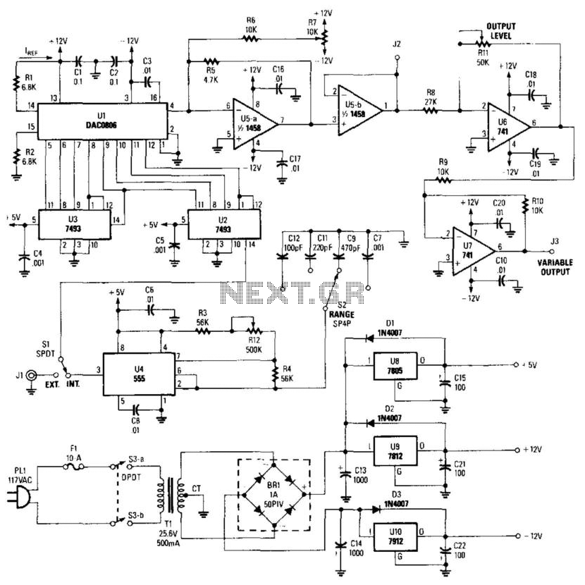
This simple circuit employs an NE555 timer configured as an oscillator, a 7493 counter chain, and a DAC0806 digital-to-analog converter. The output from the counter is fed into the DAC, resulting in a linearly increasing voltage that drives an...
The process of converting a triangle wave waveform into a sine wave involves the adjustment of its transfer function using resistors R32 and R33. Modifying these resistors affects the linearity of the response. The differential output current from the...

The circuit produces a pleasing and accurate imitation of sound, making it suitable for sound effects such as doorbells. It generates a two-tone effect that closely resembles the sound of a cuckoo. This circuit is designed to create a two-tone...
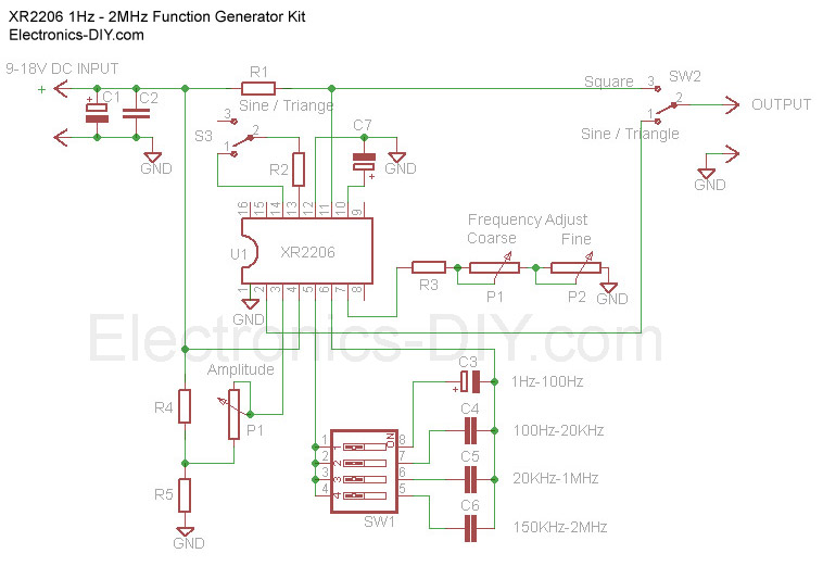
The Function Generator is essential laboratory equipment. The module described here is based on the high-quality XR2206 integrated circuit (IC). The 1Hz - 2MHz XR2206 Function Generator is capable of producing high-quality sine, square, and triangle waveforms with high...
The circuit depicted in the figure is a generator that includes an oscillator, a voltage follower, a zero amplitude adjustment, and a zero shift circuit. It is utilized as a self-balancing recorder for testing signals. The output signal ranges...
This application note describes the implementation of a single-supply triangular wave oscillator using the MAX9000 integrated circuit and several passive components. The circuit employs an operational amplifier, a comparator, and a voltage reference as the main active components. The...