
Dual timing circuit thyristor control table
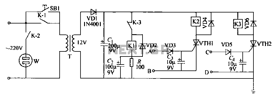
Component parameters include a 12V transformer T with a small output current that exceeds the sum of the operating currents for relays Kl, K2, and K3. Relays K1, K2, and K3 are small single-pole relays rated for 6V. The current through K2 can control the electrical power load. The thyristor should be rated for tens of milliamps. Specific component selection is illustrated in Figure 3-35, which does not require any special specifications.
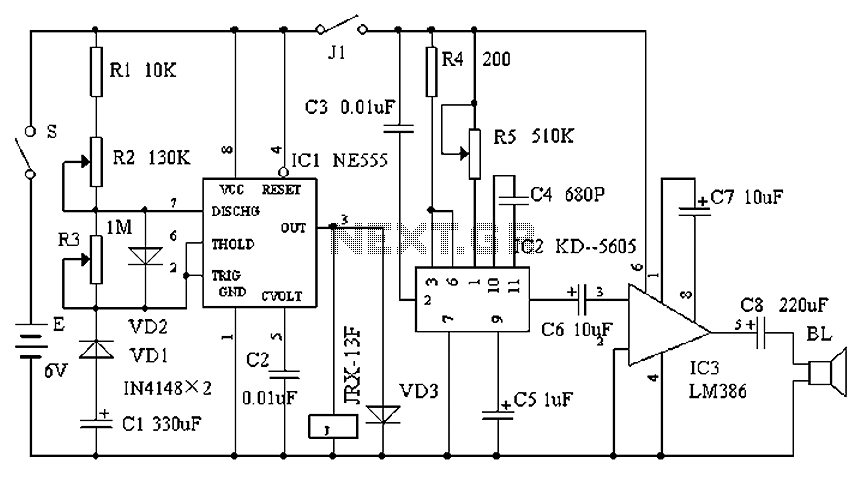
The dual timer circuit for thyristor control is depicted in Figure 3-35, illustrating how the timing mechanism operates in conjunction with the thyristor control to manage the alarm outputs effectively. The design emphasizes energy efficiency and reliability, making it suitable for various applications where alarm signaling is necessary. Each component is selected to ensure optimal performance, with careful consideration given to the operating parameters and safety features to prevent circuit failure or damage to connected devices.Electronic Table (1) Introduction This schematic circuit having two alarm output by the timer by thyristor controlled. Can any on/off, and shut down after the power supply from the transformer primary (side) power, no Depletion, safety, energy-saving, high reliability. Press the SB1 use, the power supply via T, f) 1, CI buck, rectifier filter obtained 6V DC. In this case power supply through a normally closed contact K-3 makes Kl work, normally open contacts Kl-l closed electric road self-locking. At this point after the release SB1 circuit due to self-locking and in working condition, when the timing for the start of the audio signal from the A, B input ends, the VD3, C3 triggered thyristor rectifier filter VIH1, electrical work so K2, K2 often open contact K-2 is closed.
W socket is energized, the controlled appliances are turned on. Similarly, when the timing off the audio signal of another branch Alarm clocks from C, D enters through VD5, after G rectifier trigger electrical work fH2t K3, K3 normally closed contact K-3 release disconnect, Kl loss of power, so that the normally open contacts Kl Kl release also disconnected, the entire circuit to stop working. Ri was eye resistor, C2 to Kl start capacitor, VD2, VD4, VD6 as protection diodes. (2) Component parameters 12V transformer T with a small output current is greater than Kl, K2, K3 sum of the operating current.
KJ, K2, K3 available 6V small single-pole relay. K2 contact current can be controlled by electrical power. Thyristor tens mA to use. Choice of components shown in Fig. 335, no special to the ball. (3) Dual timer circuit thyristor control table shown in Figure 3-35.
Related Circuits
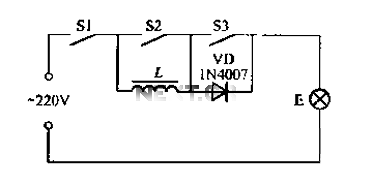
A portable four dimmer switch circuit is illustrated in Figure 8, featuring a four-speed brightness adjustment. When switches S1, S2, and S3 are all closed, the lamp operates at its brightest setting. When S1 and S2 are closed while...
The yellow wires on the far right serve as temporary power connections, allowing battery power to enter through the contact studs located in the large holes that press against the radio's battery terminals. The cable in the lower right...
Many battery-powered devices use two AA alkaline cells. Often, it is not apparent when it is time to replace the batteries until the device powered by them ceases to function. In battery-powered devices that utilize two AA alkaline cells, it...
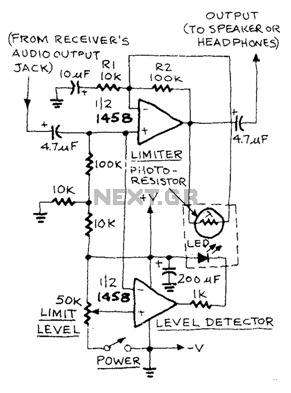
The AUD.LIMITER circuit features a level trim potentiometer that allows for adjustment of the limiting level. When the input signal exceeds the set level of the potentiometer, the output from one half of the operational amplifier, functioning as a...
Cats are natural predators of rats, and the use of electronic devices to simulate meowing sounds as a repellent is an effective method. These electronic devices can produce meowing sounds at various frequencies and intervals, making them suitable for...
This circuit is designed to support nine independent telephones using a single telephone line pair, allowing for operation at nine different locations. It includes a bidirectional telephone line simulator that does not require actual telephone lines, enabling the coupling,...