
Binary circuit diagram box
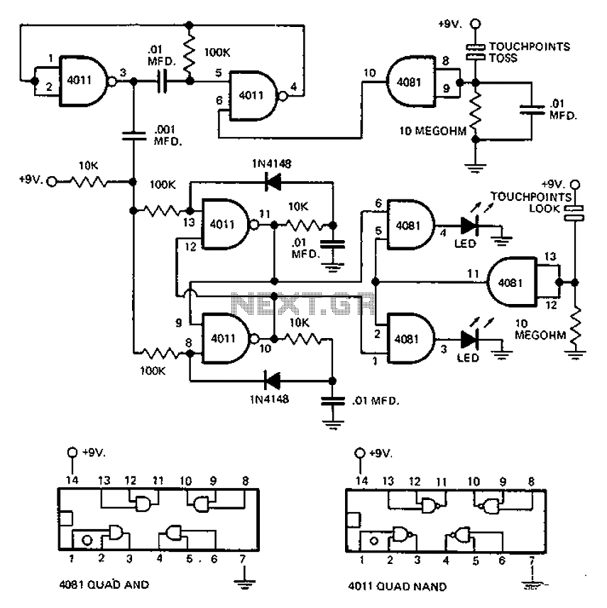
The circuit utilizes an astable multivibrator, which is a type of oscillator that continuously switches between its high and low states without requiring any external triggering. The multivibrator generates a square wave output, which can be used to drive other components or systems. The frequency of oscillation is determined by the resistors and capacitors connected to the multivibrator.
In conjunction with the astable multivibrator, a flip-flop is employed to store the state of the output signal. The flip-flop can be configured to respond to the transitions of the multivibrator's output, effectively capturing the signal state at specific intervals. This capability allows for the retention of the signal's state even after the triggering event has passed, making it useful in applications where the state needs to be preserved for further processing or control.
The combination of the astable multivibrator and the flip-flop creates a robust circuit that can be utilized in various applications, such as timing circuits, pulse width modulation, or as a basic memory element in digital systems. The design flexibility allows for adjustments in frequency and output characteristics, making it suitable for a wide range of electronic projects. Proper selection of components and configuration will ensure optimal performance and reliability of the circuit. Circuit Description: This circuit uses an astable multivibrator to change the face-up or facing negative circumstances, also uses a flip-flop, flip-flop state that there had be en a change is to be stored by multivibrator complete cycle of each of the oscillator.
Related Circuits

The YD9088 is a bipolar integrated circuit designed for use in mono portable and pocket radios. It is advantageous when minimizing peripheral components, which should be of small dimensions and low cost, is a priority. The circuit incorporates a...
The circuit utilizes the CMOS 4017 decade counter integrated circuit (IC). Each press of a switch advances the output from 0 to 9. By connecting the output through an AND gate to the subsequent IC, a specific code must...
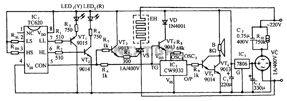
The circuit includes the TC620 temperature control circuit, the temperature indicator circuit, a thyristor-controlled heating circuit, a vocal music buck rectifier circuit, and the AC circuit. The TC620 temperature control circuit is designed to regulate temperature by monitoring the temperature...

This circuit for an intercom is a stand-alone electronic communications system designed for limited or private dialogue. The schematic illustrates the application circuit of the LM390 in the intercom configuration. Gain control can be achieved by capacitively coupling a...

Circuit characteristics: A simple phase shift range of 180 degrees, with a practical range of 170 degrees. The circuit is influenced by temperature and is suitable for small power applications in less demanding situations. The circuit operates by utilizing a...
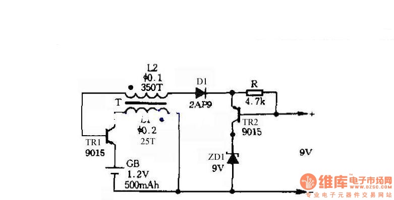
The circuit does not require a separate power switch or transformation to control the switches on the table. It offers advantages such as low power consumption, stability, reliability, and no impact on instrument accuracy. The transformer T in the...