
Bipolar power supply for battery instruments
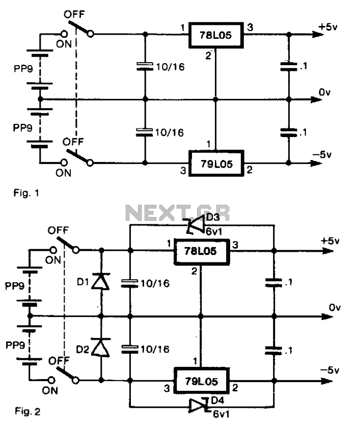
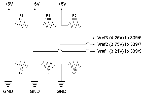
The circuit described is designed to provide dual regulated ±5-V outputs from a pair of dry batteries, which is particularly useful in applications requiring a stable voltage supply. The implementation of diodes D1 and D2 in parallel with the batteries serves as a protective measure against reverse polarity connections; this configuration allows current to bypass the batteries in the event of incorrect connection without incurring the voltage drop typically associated with series diodes.
In the circuit, the use of Zener diodes D3 and D4 is critical for maintaining the output voltage levels during the power-up sequence. These diodes ensure that the output rails are pulled up to the battery voltage until the linear regulators can stabilize the output at ±5 V. This approach prevents any potential latch-up conditions that may arise from the asynchronous activation of the regulators.
The design also accounts for the inductive or capacitive loads that may be present in the output circuit. If the load exhibits significant inductance or capacitance, turning off the supply could inadvertently apply a reverse bias to the regulators, potentially leading to damage. The inclusion of protective diodes across the regulators effectively mitigates this risk by providing a safe path for any reverse current that may occur during transient conditions.
Overall, this circuit configuration is a robust solution for generating regulated dual voltage supplies from dry batteries, with built-in protections to ensure reliable operation in various conditions. The careful selection of components, including the placement of Zener diodes and parallel diodes, contributes to the overall reliability and effectiveness of the power supply circuit.To generate regulated ± 5-V supplies from a pair of dry batteries, the circuit of Fig. 1 is commonly used. In order to give protection from inadvertent reverse connection of a battery, a diode in series with each battery would produce an unacceptable voltage drop. The more effective approach is to fit diodes Dl and D2 as shown in Fig. 2, in parallel with each battery. When the supply is switched off, there is the risk of a reverse bias being applied across the regulators, if there is significant inductance or capacitance in the load circuit.
Diodes across the regulators prevent damage. When the power supply is switched on, the two switches do not act in unison. There is a probability that one or the other regulators will be latched hard off by the other. To prevent this, D3 and D4 are Zener diodes so that ± 5-V rails are pulled up by the batteries until the regulators establish the correct levels. 🔗 External reference
Related Circuits
The circuit is designed to be installed in a small enclosure, which can be positioned according to preference. It requires only three connections: one for the positive terminal of the battery, one for the +5 volts supplied by the...
When constructing a dual stand-alone preamplifier, such as a stereo magnetic phono preamp, the power supply requirements are significantly reduced. A simple power supply circuit is illustrated, utilizing readily available 12-volt, 0.5-ampere transformers, although units capable of 1 ampere...
This power supply circuit is designed around a standard 12VAC landscape lighting transformer. The availability and selection of transformers have long posed challenges for experimenters, often leading them to use potentially hazardous off-line capacitor-limited power supplies. However, the widely...
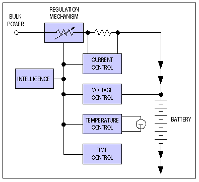
Application note on designing linear and switch-mode (switching DC-DC converter current source) battery charger applications that require external microcontrollers and related system-level issues for notebook computers. The application note provides guidance on the design of both linear and switching DC-DC...
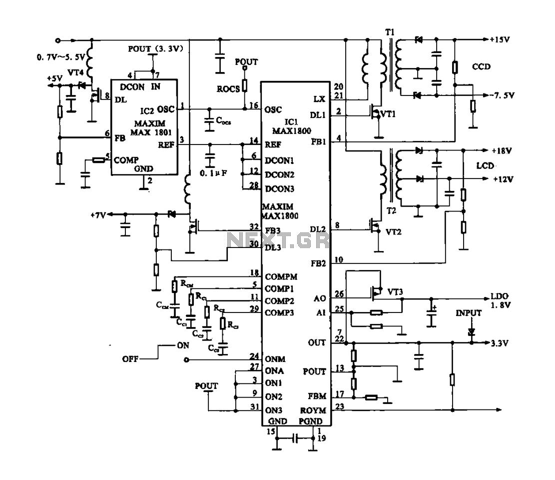
Digital Cameras - DV machine power supply circuit. This circuit utilizes the MAX1800 chip to manage the power supply for digital cameras and DV machines. Digital cameras are typically battery-operated and require low voltages ranging from 0.7 to 5.5...
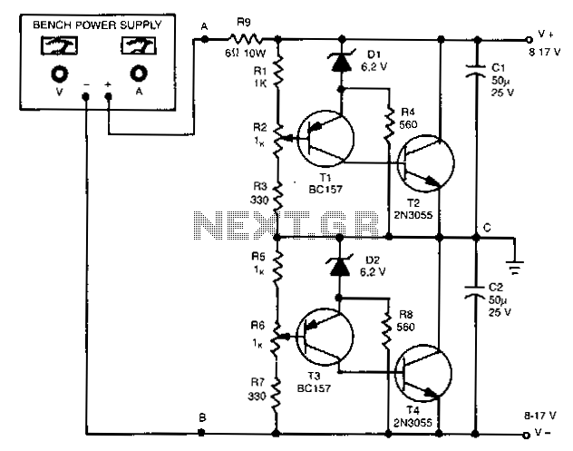
The outputs in this circuit are independently variable and can be loaded unsymmetrically. The output voltage remains constant, regardless of load and changes. By varying potentiometers R2 or R6, the output voltages can be conveniently set. Outputs can be...
Warning: include(partials/cookie-banner.php): Failed to open stream: Permission denied in /var/www/html/nextgr/view-circuit.php on line 713
Warning: include(): Failed opening 'partials/cookie-banner.php' for inclusion (include_path='.:/usr/share/php') in /var/www/html/nextgr/view-circuit.php on line 713