
Digital Cameras -DV machine power supply circuit
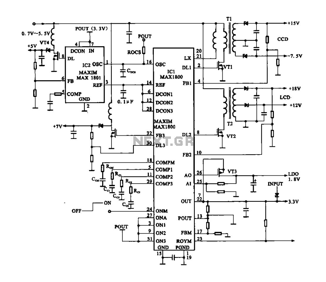
The power supply circuit for digital cameras and DV machines is designed to efficiently convert low battery voltages into the higher voltages required by the camera's internal components. The MAX1800 chip is central to this operation, utilizing Pulse Width Modulation (PWM) to control the switching of a transformer. This method allows for the generation of multiple output voltages, which are essential for powering various parts of the camera, such as the image sensor, processing unit, and display.
The circuit begins with the battery supplying a low voltage, which is fed into the MAX1800. This chip regulates the input and generates PWM signals that control the operation of the transformer. The transformer steps up the voltage to the required levels through a process of inductive boosting. The outputs of the transformer are then rectified and filtered to provide stable DC voltages of +18 V, +15 V, +12 V, -7.5 V, +1.8 V, and +3.3 V.
The design of this power supply circuit emphasizes efficiency and reliability, ensuring that the digital camera can operate effectively under varying conditions. The inclusion of multiple output voltages allows for versatile application in different camera models and configurations. Additionally, the recommended output voltage from IC2 is crucial for maintaining optimal performance and preventing damage to sensitive components. Overall, this circuit exemplifies the integration of advanced power management techniques in modern digital devices.Digital Cameras -DV machine power supply circuit It shows a digital camera/DV machine power supply circuit, the circuit MAX1800 chip to control the core. The figure shows that digital cameras are battery-powered. Low voltage (0.7 ~ 5.5 V). But the circuit inside a digital camera often requires a higher voltage, such as +18 V, + 15 V, + 1V and the like. To this end the use of digital cameras MAX1800 Li iJ chip PWM signal, and by boosting the way open after two off pulses via a switch transformer (TI, T2) output + 18V, + 15V, + 12V, -7.5V, also outputs + 1.8V and 3.3V DC voltage.
At the same time recommended by the IC2 +V output voltage.
Related Circuits
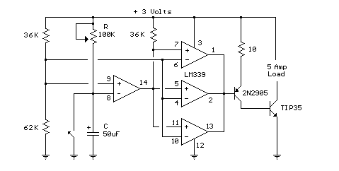
This circuit utilizes an LM339 quad voltage comparator to create a time delay and manage a high current output at low voltage levels. Approximately 5 amps of current can be sourced using a pair of fresh alkaline D batteries....
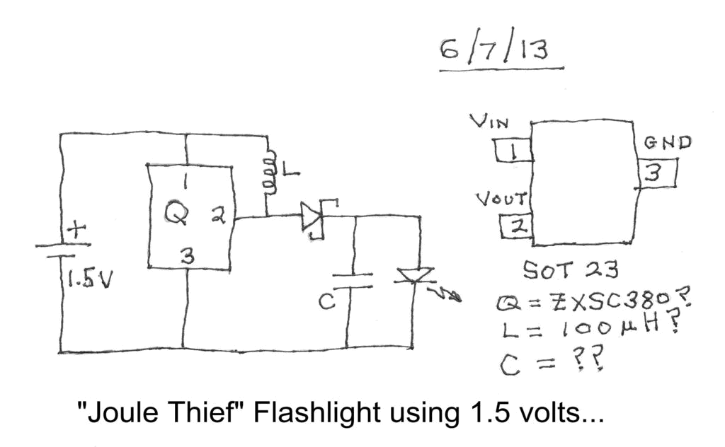
Investigating a Paradox: Recently, an energy-saving LED flashlight was observed for sale that utilized only one 1.5-volt battery. Upon purchasing this light and disassembling it, the expectation was to find a battery, bulb, switch, and a circuit board designed...
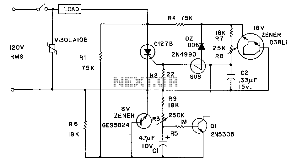
Industrial applications sometimes require that power be briefly applied to a load following the closure of a switch, such as a microswitch or foot switch. The load could be a heating element used for sealing plastic bags, a DC...
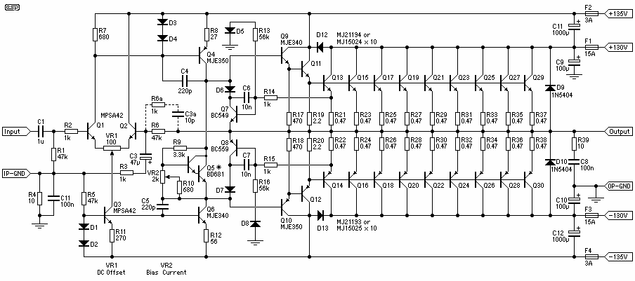
Capable of 2kW peak and a minimum of 1.5kW continuous, it has to be said that this amplifier will blow up any speaker connected to it. Regardless of the claimed power that various drivers can handle, they can't. To...
The core multi-resonant circuit 40 L06 has a collapse time of 1C. An auxiliary electric signal operates below its low threshold, opening Icl. The output is provided through two terminals for business use. The circuit includes components such as...
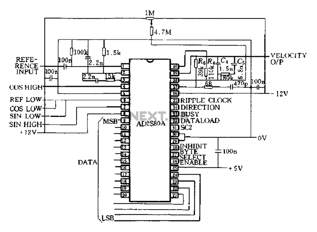
The AD2S80A represents a typical application circuit, detailing specific peripheral connectivity and device parameters. It is configured for a 12-bit resolution (SCl-0, Sc2 1) to select a reference frequency of 5 kHz. The bandwidth is 520 Hz, with a...
Warning: include(partials/cookie-banner.php): Failed to open stream: Permission denied in /var/www/html/nextgr/view-circuit.php on line 713
Warning: include(): Failed opening 'partials/cookie-banner.php' for inclusion (include_path='.:/usr/share/php') in /var/www/html/nextgr/view-circuit.php on line 713