
Bipolar Stepper Motor Driver Circuit
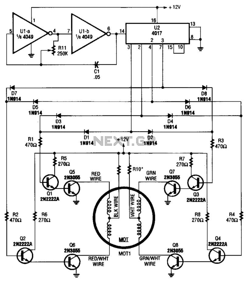
The circuit utilizes a 4017 decade counter to sequentially activate transistor switches that control the windings of a 12-V stepper motor (MOT1). The low-frequency oscillator, comprising operational amplifiers U1-a and U1-b, generates the clock signals necessary for the counter's operation. The output of the 4017 activates the transistors in a specific sequence, allowing for precise control of the motor's movement.
Resistors R9 and R10 are critical components selected to match the current requirements of the stepper motor. These resistors ensure that the transistors operate within their safe limits, preventing overheating or damage due to excessive current. The choice of these resistors is based on the motor's specifications, particularly its rated current.
The frequency of the oscillator directly influences the speed of the stepper motor. For instance, a 3.3-Hz clock signal results in a motor speed of 1 rpm, while increasing the frequency to 33 Hz allows the motor to operate at 10 rpm. This relationship between frequency and motor speed can be utilized to achieve various operational speeds by adjusting the oscillator's frequency output. The design provides flexibility in controlling the motor's speed, making it suitable for applications requiring precise movement and positioning.
Overall, this circuit design effectively integrates a decade counter, low-frequency oscillator, and transistor switches to control a stepper motor, demonstrating a practical approach to motor control in electronic applications. A 4017 decade counter/divider driven from a low-frequency oscillator (Ul-a and Ul-b) is used to drive transistor switches to sequence the windings, as is needed. MOT1 is a 12-V stepper motor. R9 and RIO are selected for the motor`s current rating. A 3.3-Hz signal from Ul will cause the motor to run at 1 rpm, a 33-Hz signal will result in 10 rpm, etc. 🔗 External reference
Related Circuits
Design a circuit using a power MOSFET to replace the NTC thermistor that many Mag623 users employ to prevent their bulbs from flashing. Although inexpensive and easy to connect, NTCs run quite hot, are affected by ambient temperature, require...
The purpose of this circuit is for research and education. Assistance is sought in acquiring components for simple RF circuits, as well as tutorials or schematics. The requester is facing challenges in locating quality resources for beginner-level RF circuit...
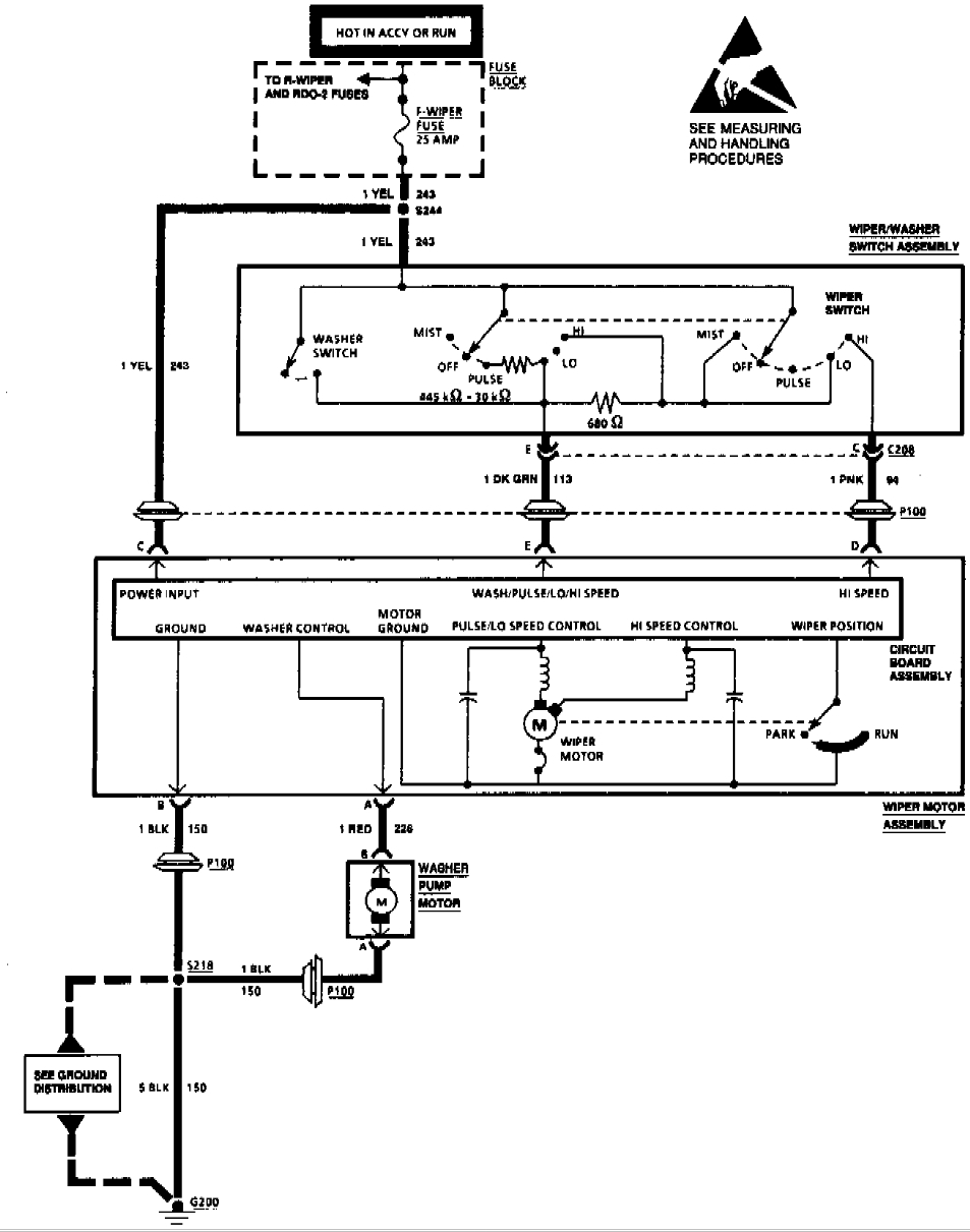
A 1994 Pontiac Transport has an issue where the front wipers only operate on the high setting. A suggestion has been made that a wiper motor replacement may be necessary, while another opinion indicates that the wiper pulse module...
The circuit was taken from an old Elektor electronics magazine and is a compact design suitable for generating high-intensity lighting effects during festivals, parties, and gatherings. Diodes D1 and D2, along with capacitors C1 and C2, form a voltage...
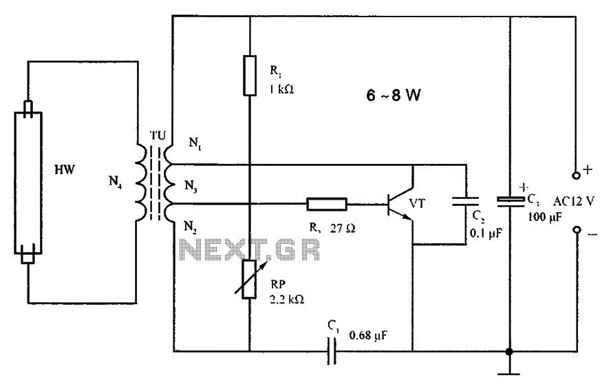
The lighting inverter circuit is designed for 6 to 8W fluorescent tubes. This circuit is appropriate for powering fluorescent tube circuits within the specified wattage. The parameters for the circuit are indicated in the accompanying figure. When utilizing a...

This is an FM wireless transmitter circuit designed to operate a microphone without the need for a cable connecting the microphone to the amplifier. The FM wireless transmitter circuit typically consists of several key components: a microphone, an oscillator, a...