
FM wireless transmitter circuit

The FM wireless transmitter circuit typically consists of several key components: a microphone, an oscillator, a modulator, and an antenna. The microphone captures sound waves and converts them into electrical signals. These electrical signals are then fed into the oscillator, which generates a carrier frequency. The modulator combines the audio signal from the microphone with the carrier frequency produced by the oscillator, effectively encoding the audio information onto the carrier wave.
The output of the modulator is then transmitted through an antenna, which radiates the modulated signal as electromagnetic waves. The design of the antenna is crucial for ensuring efficient transmission and reception of the signal. The circuit may also include additional elements such as filters to remove unwanted frequencies, amplifiers to boost the signal strength, and power supply components to ensure stable operation.
In practical applications, the FM wireless transmitter circuit is widely used in various audio transmission scenarios, including public speaking, musical performances, and broadcasting. The absence of a physical connection between the microphone and the amplifier provides greater freedom of movement for the user while maintaining high audio quality. Proper tuning of the circuit is essential to achieve optimal performance, with considerations for frequency stability, range, and audio fidelity.This the fm wireless transmitter circuit, the truth is one kind microphone that developed to be used without a cable from the microphone to the amplifier. Makes.. 🔗 External reference
Related Circuits
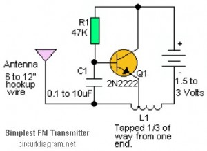
This is likely the simplest radio transmitter available, consisting of five components and capable of being assembled in a compact space. It is suitable for science fair projects or other science-related endeavors where short-range transmission is beneficial. The device...

This design outlines a phone bug circuit. The wireless telephone line spy circuit is capable of transmitting phone conversations to a nearby FM radio. The circuit must be connected to a standard phone line. In the circuit, the first...
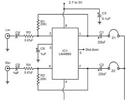
The LM4880 is a dual audio HiFi amplifier integrated circuit from National Semiconductor. This headphone amplifier circuit is specifically designed to produce high-quality audio output with a minimal number of components. The LM4880 integrated circuit is capable of delivering...
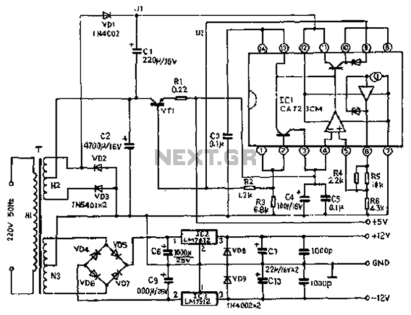
The circuit depicted features a secondary N3 center tap transformer (T) with a common point connecting diodes VD2 and VD3 to positive electrodes, along with capacitors C2, C6, C7, and negative electrodes connected to capacitors C9 and C10. Additional...
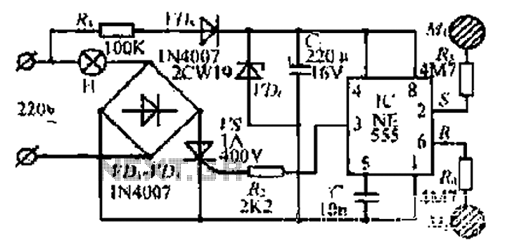
220V AC by Ri buck, Diao. C1 chain ferry flood ear, shouted for the regulator to 12V make C collapse. The film hand touch under ridicule the MT electrode films, clutter body. More: induction signal sent by See Cutting...
Many applications require low-frequency signal generators that can deliver high-performance, high-resolution signals. This design idea presents a circuit that generates frequencies from 0 to 1 MHz, providing sinusoidal, triangular, and square-wave outputs with frequency resolution better than 0. A...