
mains ac xenon tube flasher circuit

The described circuit utilizes a voltage doubler configuration, which is an effective method for increasing the voltage from a low-voltage AC source. The diodes D1 and D2 are arranged in such a way that they rectify the AC input, while capacitors C1 and C2 store and double the voltage, ensuring that the circuit can produce a sufficient voltage to trigger the xenon gas tube.
The xenon gas tube operates based on the principle of gas discharge. When the voltage across the anode and cathode reaches a certain threshold, the inert gas ionizes, allowing current to flow through the tube. The metal ring serves as a trigger point; when a pulse is applied, it initiates the discharge process. The resulting arc creates a bright flash of light, which is ideal for visual effects in various events.
To ensure proper functionality, the circuit should be designed with appropriate values for the diodes and capacitors to handle the expected input voltage and current. The choice of diodes should consider their reverse voltage ratings and forward current capacities. Capacitor values must be selected to provide adequate energy storage while considering the ripple voltage and discharge characteristics.
Safety precautions are critical when working with high voltages, especially in circuits involving gas discharge tubes. Proper insulation and protective components should be utilized to prevent accidental contact with live parts. Additionally, the circuit should be housed in a suitable enclosure to protect users from electric shock and to contain any potential hazards associated with the operation of the xenon tube.
In summary, this circuit design is a practical solution for generating high-intensity lighting effects, leveraging a voltage doubler configuration and the unique properties of a xenon gas tube. Proper component selection and safety measures are essential for reliable and safe operation.The circuit was taken from one of the old elektor electronics magazine and it is indeed a very cute little circuit which may be used for creating high intensity lighting effects during festivals, parties and fun gatherings. Diodes D1 and D2 along with the capacitors C1 and C2 form a voltage doubler circuit which creates a voltage level twice the v
alue of the input voltage (across C1/C2). As the name suggests, its a tube filled with inert xenon gas. A metal ring is attached toward the anode side of the tube which becomes the gate trigger point of the device. Thisring isterminatedwith a wire so that it can be connected with s pulse source. When a high voltage is set across the anode/cathode pins of the tube and a pulse applied across the trigger gate wire and cathode, the tube gets charged up and allows the whole voltage across its Anode.
cathode to pass through creating an intense arc lighting inside the tube due to thepassageof the high speed electrons through the xenon gas. 🔗 External reference
Related Circuits
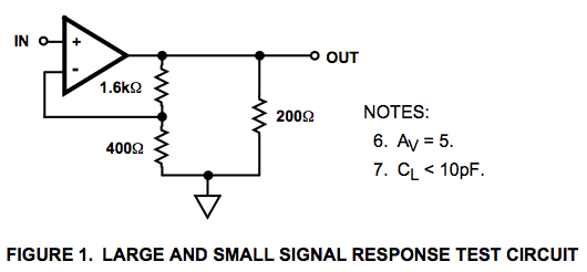
Here is a circuit diagram for a signal response test circuit from the specification sheet for a HA-5195 operational amplifier. It appears to be a non-inverting amplifier circuit with a gain of 5, along with a 200-ohm resistor connecting...
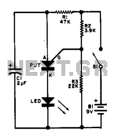
This flasher circuit functions as a relaxation oscillator, with capacitor C1 discharging periodically through the LED when the Programmable Unijunction Transistor (PUT) is activated. The flashing rate is approximately 100 times per minute, based on the specified component values. The...
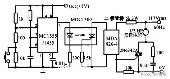
The switch shut-off time delay circuit consists of a timer, optocouplers, a bridge SCR, and an SCR AC switch. When the control button is released, it allows the motor or other AC power to remain active for one hour....
Fading a video signal cannot be achieved merely by attenuating the composite signal, as this may cause the synchronization signal to fall below an unacceptable level. To effectively fade a video signal while maintaining the integrity of the synchronization...
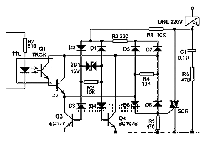
The relay illustrated in the figure operates based on non-inductive analog circuit theory. Its working principle involves a 220V power supply connected to a load (RL), resistors (R1, R3, R6), diodes (D1 to D8), and a zener diode (ZD1)....
LEDs lining the headliner will fade in when the door is opened and fade out when the door is closed. The necessary components include a circuit to utilize 12V power from the vehicle to illuminate 15 LEDs and control...