
Bipolar Transistor HBridge Motor Driver
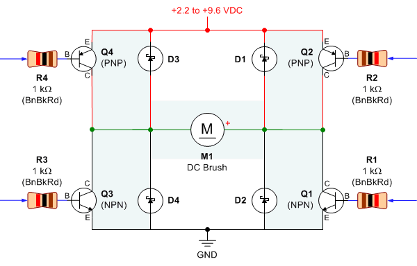
The classic bipolar H-bridge motor driver circuit is a widely used configuration that allows for the control of DC motors in both forward and reverse directions. This circuit utilizes four transistors arranged in a bridge configuration, which enables the reversal of current flow through the motor. The schematic representation of this circuit typically includes the four transistors, which can be either bipolar junction transistors (BJTs) or MOSFETs, depending on the desired characteristics and performance requirements.
In the breadboard photo, the physical layout of the circuit can be observed, showcasing the arrangement of components, including the transistors, resistors, diodes, and the motor. The breadboard setup is essential for prototyping and testing the circuit before finalizing the design on a printed circuit board (PCB).
The parts list includes all necessary components for constructing the H-bridge motor driver circuit. This typically encompasses the transistors, resistors for base or gate control, flyback diodes to protect against voltage spikes generated by the motor, and any additional components necessary for proper operation, such as capacitors for filtering.
The results of several transistor variations indicate the performance differences when using different types of transistors. For instance, BJTs may provide different switching characteristics compared to MOSFETs, affecting efficiency, heat dissipation, and response time. Testing various configurations allows for optimization of the circuit for specific applications, ensuring reliable operation under varying load conditions.
Overall, the combination of the schematic, breadboard photo, parts list, and experimental results provides a comprehensive overview of the classic bipolar H-bridge motor driver circuit, facilitating understanding and implementation in various electronic projects.Schematic, breadboard photo, parts list, and results of several transistor variations on the classic bipolar hbridge motor driver circuit.. 🔗 External reference
Related Circuits
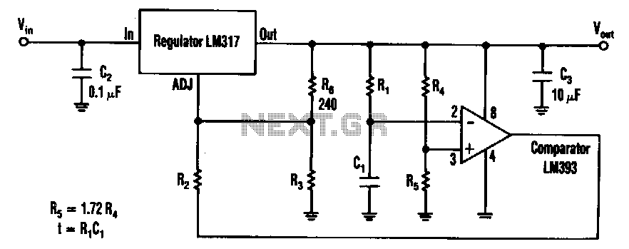
The timed two-voltage circuit can start and run a small DC motor or solenoid. The input voltage to the LM317 three-terminal regulator ranges from 5 to 40 V, and the output voltage can range from 2 to 36 V....
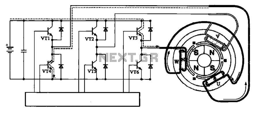
The brushless motor consists of a rotor, a stator, and a drive circuit. The relationship between the brushless motor rotor, stator, and drive circuit is illustrated in the accompanying figure. In the initial state, VT3 and VT4 are conducting,...
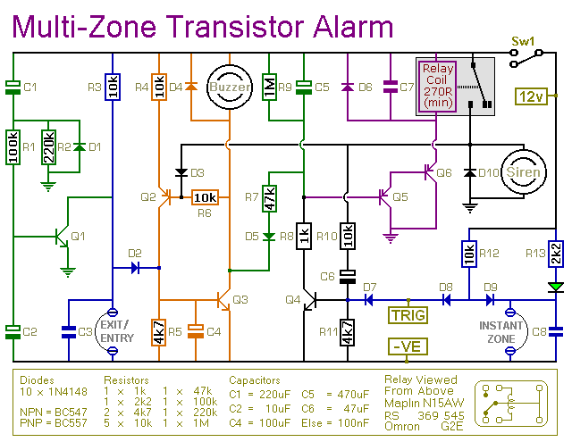
This transistor-based alarm features automatic exit and entry delays, along with a timed bell cut-off and system reset. In addition to the exit/entry zone, the basic alarm board includes one instant zone, which is sufficient for many applications. However,...
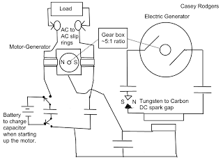
Locate Permanent Magnet DC Generators, Magnetic Motor Generators, and additional information at Magneticgenerator.info. Discover the best options for Free Energy Magnet Motors, explore topics such as Cash Advances, browse the Debt Consolidation section, or learn about Insurance. Magneticgenerator.info serves...
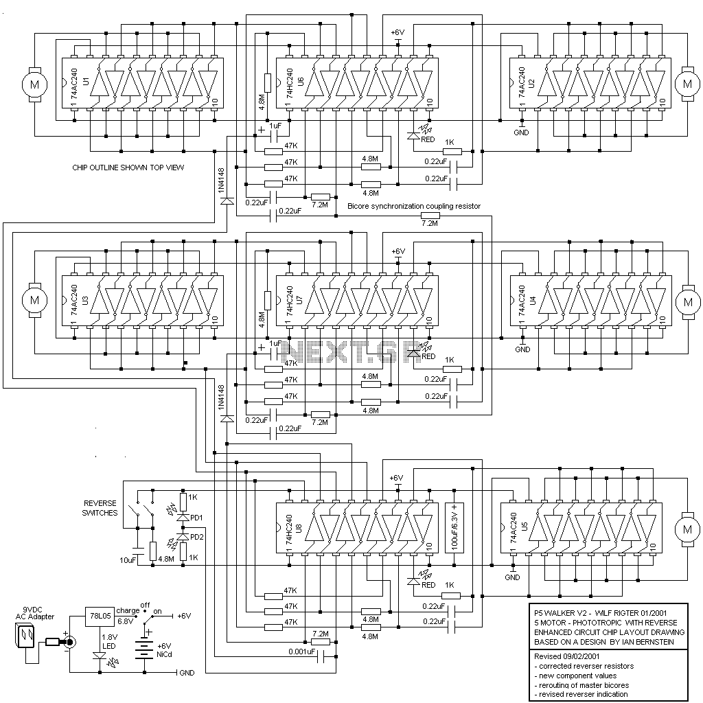
The P5 design utilizes eight 74HC/AC240 chips, which function as octal inverting buffers. Each 74HC/AC240 chip contains two groups of four inverters, each managed by a tri-state enable pin (pins 1 and 19). The 74AC240 chips (U1-U5) serve as...
This page is provided to the domain owner free by Sedo's Domain Parking. Disclaimer: The domain owner and Sedo maintain no relationship with third-party advertisers. References to any specific service or trademark are not controlled by Sedo or the...