
An Expandable Transistor Based Burglar Alarm circuit
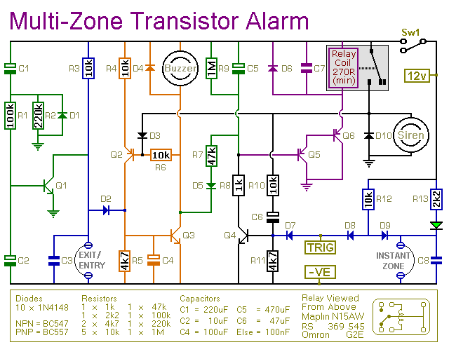
The described alarm system utilizes a transistor-based circuit to manage various functions essential for security and user convenience. The automatic exit and entry delays serve to provide users with sufficient time to leave or enter the protected area without triggering the alarm unintentionally. This feature is critical in residential and commercial applications where users may need to disarm the system upon entry.
The system incorporates a timed bell cut-off function that prevents the alarm from sounding indefinitely. This feature enhances user comfort by ensuring that alarms are not excessively disruptive, thus allowing for a reasonable period for the user to respond to the alarm condition. The system reset function provides a straightforward method for users to reset the alarm after it has been triggered, ensuring that the system can quickly return to its standby state.
The basic alarm board includes one instant zone, which is designed to trigger the alarm immediately upon detection of an unauthorized entry. This zone is particularly useful for high-security areas where immediate alerting is necessary. The modular design of the system is a significant advantage, as it allows for scalability. Users can expand the system by integrating additional zones as required, enhancing the overall security coverage.
The mention of a four-zone expansion module suggests that the system can be customized to meet specific security needs. Each zone can be configured to respond differently based on the security requirements of the area it monitors. For instance, additional zones could be programmed for different types of sensors, such as motion detectors or door/window contacts, allowing for a comprehensive security solution tailored to the user's environment.
Overall, this transistor-based alarm system presents a flexible and efficient solution for security applications, offering essential features that can be adapted to various scenarios through its modular design.This transistor based alarm features automatic Exit and Entry delays - together with a timed Bell Cut-off and system Reset. Along with the Exit/Entry zone - the basic alarm board has one Instant Zone. This will be adequate in many situations. However - the modular design means that it`s easy to add as many zones as you like to the system. Details of a Four-Zone expansion module are provided.. 🔗 External reference
Related Circuits
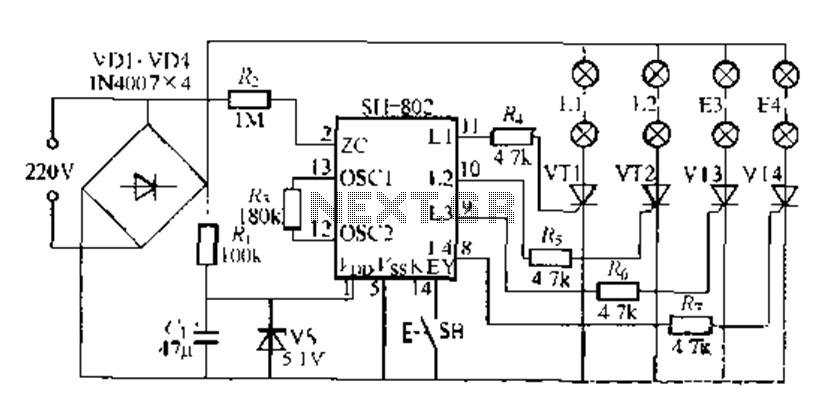
A digital integrated circuit simplifies the response process significantly. The diagram illustrates a circuit comprising four responder groups. The digital integrated circuit described serves as a crucial component in various electronic systems, primarily focusing on enhancing response efficiency. It comprises...
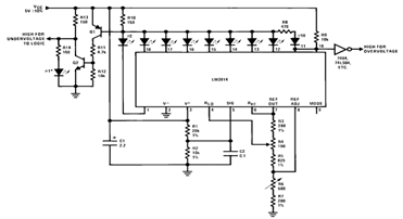
By utilizing several resistors, LEDs, and the LM3914 bar/dot display driver IC, it is possible to create a straightforward 5V voltmeter monitor circuit. This circuit offers TTL-compatible undervoltage and overvoltage warning signals. A complete circuit schematic is available below. The...

This is the first electronic circuit designed from scratch, marking the initial experience with programming a microcontroller (MCU), the first application written in assembly language, and the second homemade printed circuit board (PCB). While it is common for individuals...

Discrete Class AB Transistor Audio Power Amplifier Circuit Diagram. This is a Class AB transistor power amplifier. It is a simple amplifier to... A Class AB transistor audio power amplifier is designed to provide high-quality amplification for audio signals while...
In this circuit, two 567 tone decoders are utilized. One functions as an oscillator, while the other acts as a detector. Connecting TP1 and TP2 allows U2 to receive the signal from U1, resulting in pin 8 of U2...

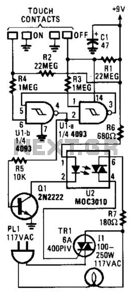
When the touch-on contacts are bridged, pin 6 of U1 goes low, which forces its output (the set output) at pin 4 to go high. That high divides along two paths; in one path, the output is applied to...