
Brushless motor rotor a stator and a drive circuit
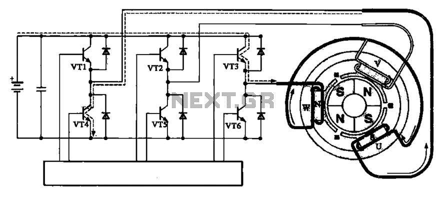
The brushless motor operates on the principle of electromagnetic induction, utilizing a rotor and stator configuration to achieve efficient motion without the need for brushes. The rotor, typically composed of permanent magnets, interacts with the stator's electromagnetic fields generated by the drive circuit. The drive circuit comprises a series of transistors (VT1 to VT6) that control the current flow through various coils (W, U, and V), which are arranged in a specific sequence to create rotating magnetic fields.
In the initial state of the motor, VT3 and VT4 are activated, allowing current to flow through coils W and U. This configuration generates a magnetic field that establishes the N and S poles of the stator, facilitating the rotor's movement. The rotor, influenced by this magnetic field, begins to rotate counterclockwise. As the rotor reaches a predetermined speed of 600 RPM, the system transitions by turning on VT1 and VT5. This change modifies the current path, effectively reversing the magnetic polarities at the coils. The result is that the magnetic field at coil U becomes an N-pole while coil V becomes an S-pole, which sustains the rotor's counterclockwise rotation.
The ability to switch the states of the transistors in a precise sequence is crucial for maintaining continuous motion. The drive circuit must be designed to ensure that the transistors operate in a coordinated manner, allowing for smooth transitions and preventing stalling or backtracking of the rotor. This is achieved through the use of a microcontroller or dedicated driver ICs that manage the timing and sequencing of the transistor activations.
Overall, the brushless motor design emphasizes efficiency, reliability, and low maintenance, making it suitable for a variety of applications in robotics, automotive, and industrial automation. The absence of brushes reduces wear and tear, leading to a longer lifespan and improved performance compared to traditional brushed motors. Brushless motor rotor, a stator and a drive circuit Relationship between the brushless motor rotor, a stator and a drive circuit is shown in Fig. The initial state illustrated VT3, VT4 conduction, the power of the positive electrode via a W coil U coil VT3 VT4 a negative electrode to form a loop, loop forming stator poles W N pole, U S coil forming pole, V coil no current. As the role of the stator magnetic field on the rotor poles, the rotor is rotated counterclockwise. When it runs 600, VT1, VT5 from off into a conduction state, the current path is changed, that is a positive power supply VT1 a coil winding U V VT5-- a negative power.
U magnetic coil at the first field becomes N-pole magnetic field at the coil becomes V S, so that the rotor continues to rotate counterclockwise direction (600). After VTl ~ VT6 crystal tube orderly handover can be achieved continuous rotation.
Related Circuits
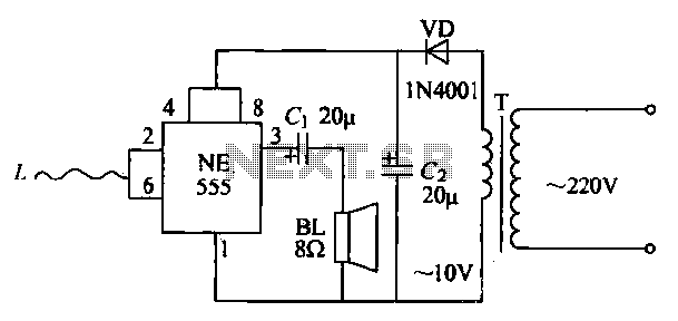
The manpower inductive alarm circuit is simple and practical. When a person's hand approaches the sensing line, the alarm emits a sound, making it suitable for male electrical burglar alarms. The induction line L is approximately 50 cm long....
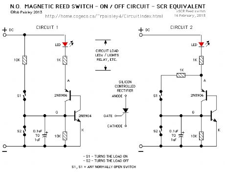
This is a very simple project using a printed circuit board and 8 components. It will flash an ordinary 3mm or 5mm (1/8" or 1/4") LED at a rate of about one flash per second. This circuit works on...
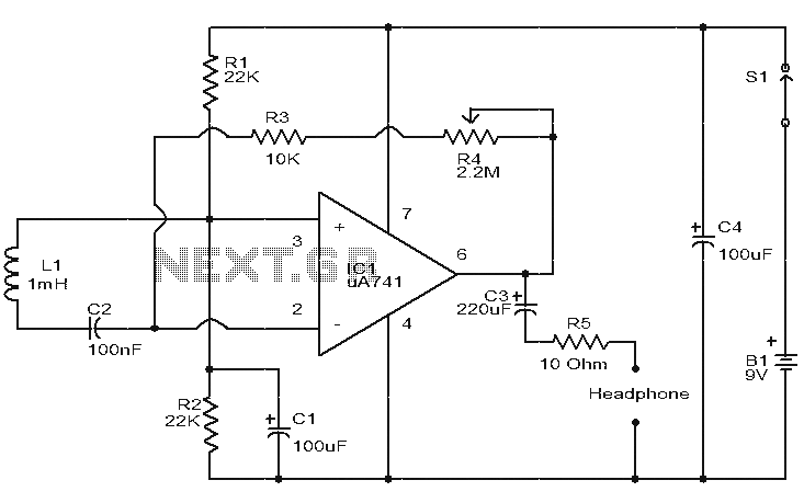
This is a simple circuit designed to detect electromagnetic radiation, including hidden wiring. It utilizes a 1mH inductor to sense the electric field. The induced voltage from the inductor is amplified by an operational amplifier (op-amp). An audio headset...
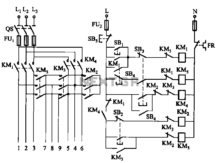
The circuit illustrated in Figure 3-62 is a manually controlled step-down start button circuit. Upon startup, the initial motor windings are configured in a Y-shape. Subsequently, the configuration transitions to a Yanbian shape (2:1), followed by a Yanbian shape...
The SS0001 human pyroelectric voice alarm circuit diagram is designed for use as a pyroelectric infrared warning device, which can help prevent electric shock or theft. With minor modifications, it can also function as an automatic light switch. This...
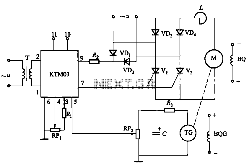
The adjustment potentiometer for the Raspberry Pi can modify the conduction angle of the thyristor VI and V2, which in turn adjusts the speed of the DC motor M. The speed feedback circuit is implemented using a tachometer generator...
Warning: include(partials/cookie-banner.php): Failed to open stream: Permission denied in /var/www/html/nextgr/view-circuit.php on line 713
Warning: include(): Failed opening 'partials/cookie-banner.php' for inclusion (include_path='.:/usr/share/php') in /var/www/html/nextgr/view-circuit.php on line 713