
BIQUAD AUDIO FILTER
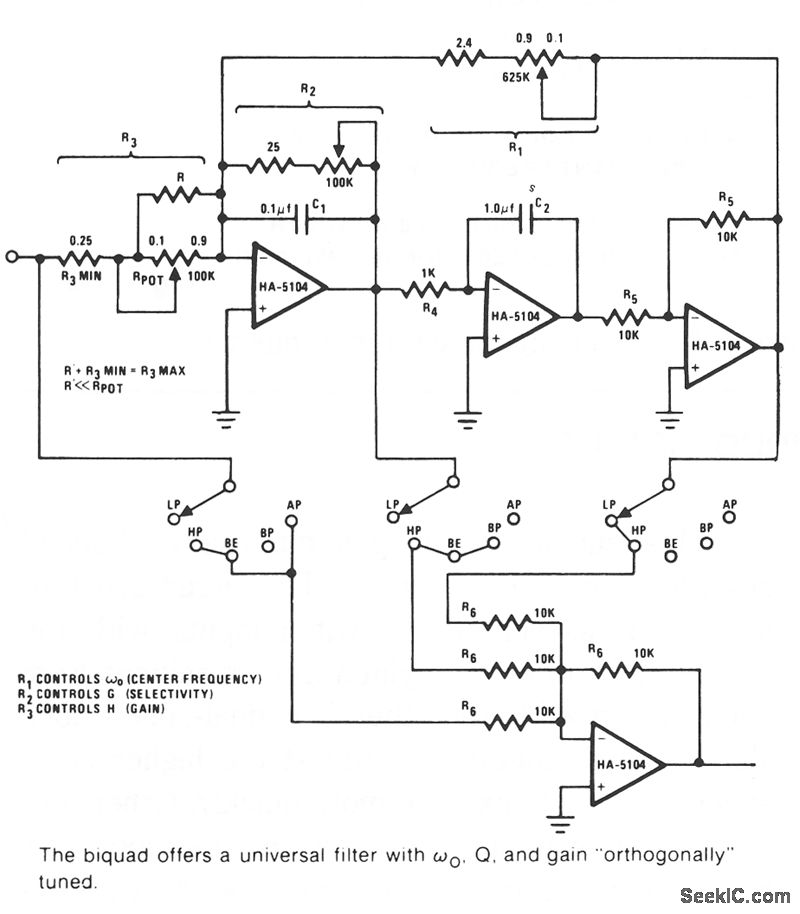
The Biquad filter is a versatile electronic filter configuration that consists of two integration stages followed by an inverting stage. The feedback loop is a critical aspect of its design, as it ensures stability and control over the filter's frequency response. The resistor R1 is pivotal in determining the center frequency, fo, which is the frequency at which the filter exhibits peak response.
In the first integration stage, the performance is limited by resistor R2, which restricts the integrator's range. The combination of resistor R2 and capacitor C establishes the time constant for this stage, effectively defining how quickly the filter responds to changes in the input signal. Resistor R3 plays a significant role as it directly influences the gain H of the filter, allowing for adjustments in the output amplitude.
The Biquad filter's ability to generate both band-pass and low-pass functions is achieved through strategic placement of the filter stages. The band-pass function is taken from the output of the first integration stage, while the low-pass function is extracted after the third stage. This configuration allows for complex filtering operations that can be tailored to specific audio applications.
The orthogonal tuning capability of the Biquad filter is one of its standout features, as it allows for independent manipulation of the center frequency (fo), quality factor (Q), and gain (H). This flexibility is essential for audio applications where precise control over frequency response is required. The component values are designed to facilitate a center frequency range from 40 Hz to 20 kHz, making the Biquad filter suitable for a wide variety of audio filtering tasks. By adjusting resistors R1, R2, and R3 in succession, users can finely tune the filter characteristics to meet their specific needs, ensuring optimal performance in diverse audio environments.The Biquad consists of two successive integration stages followed by an inverting stage. The entire group has a feedback loop from the front to the back consisting of R1 which is chiefly responsible for controlling the center frequency, ‰o. The first stage of integration is a poor integrator because R2 limits the range of integration. R2 and C fo rm the time constant of the first stage integrator with R3 influencing gain H almost directly. The band-pass function is taken after the ftrst stage with the lowpass function taken after the third stage. The remaining ftlter operations are generated by various combinations of three stages. The Biquad is orthogonally tuned, meaning that ‰o. Q. and gain H can all be independently adjusted. The component values known will allow ‰o, to range from 40 Hz to 20 kHz. The other component values give an adequate range of operation to allow for virtually universal filtering in the audio region.
‰o Q. and gain H can all be independently adjusted by tuning R1 through R3 in succession. 🔗 External reference
Related Circuits
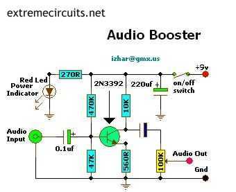
This small amplifier circuit is ideal for boosting small audio units. The small amplifier circuit is designed to enhance the audio signals from low-output devices, such as microphones or portable music players. It typically employs a transistor or an operational...
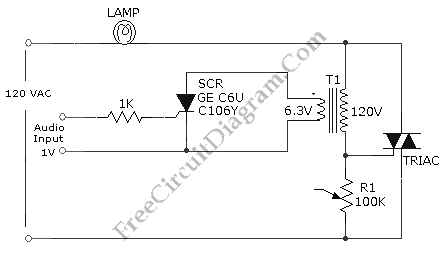
This is an audio-controlled lamp circuit. This circuit requires a low voltage input, such as from pre-amplifiers, tone control, or general audio line level output. The audio-controlled lamp circuit is designed to activate a lamp in response to audio signals....
This project is probably the most ambitious so far, and can be expected to be very expensive. On the positive side, it is also capable of excellent performance, and can be tailored to suit your exact specifications. There are...
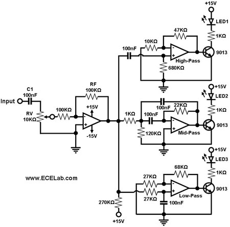
Figure 1 illustrates a simple circuit designed for converting an audio signal (such as one from the output terminals of a CD player). The circuit primarily consists of a buffer/amplifier stage and three filtering circuits: a high-pass filter, a...
This low noise audio power supply circuit can reduce noise and ripple voltage by 40 dB over the 100 Hz to 20 kHz audio range. In portable applications such as... This low noise audio power supply circuit is designed to...
This is a Class D audio amplifier circuit that is used to control PWM motor speed. This circuit has two advantages for battery-powered portable devices. First, The Class D audio amplifier circuit is designed to efficiently manage the speed...