
Audio Simple Sound-to-Light Converter Schematic Diagram
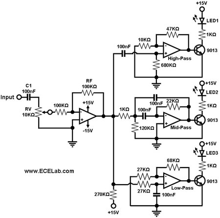
The circuit design begins with a buffer/amplifier stage, which is essential for isolating the input audio signal from the subsequent filtering stages. The buffer ensures that the audio source is not loaded down by the filters, maintaining signal integrity. The capacitor C1 is crucial for coupling the audio signal while blocking any DC offset that may be present.
Following the buffer, the circuit branches into three distinct filtering paths. The low-pass filter is designed to allow signals below a certain cutoff frequency to pass through while attenuating higher frequencies. This is typically achieved using a combination of resistors and capacitors configured in an RC network. The output of the low-pass filter is connected to an LED that illuminates in response to bass frequencies.
The band-pass filter, situated in the middle path, is engineered to pass a specific range of frequencies, effectively allowing mid-range audio signals to be processed. This filter is often implemented using a more complex arrangement of components to ensure that both the lower and upper cutoff frequencies are precisely defined. The corresponding LED for this filter responds to mid-range frequencies, providing visual feedback on the audio signal's presence in that frequency band.
The high-pass filter, located at the top of the circuit, permits signals above a certain frequency to pass while blocking lower frequencies. Similar to the low-pass filter, this is achieved through an RC network, and its output drives an LED that lights up in response to treble frequencies.
The interaction of these filters with the audio signal creates a dynamic visual representation of the audio content. As the audio signal varies, the corresponding LEDs flicker in intensity, creating a captivating effect that reflects the frequency content of the music. This circuit can be used in various applications, including visualizers for audio systems, decorative lighting, or educational demonstrations of audio frequency response. Proper selection of component values is crucial for achieving the desired performance and ensuring that the circuit operates effectively across the intended frequency ranges.Figure 1 shows a simple ambit for converting an audio arresting (such as one that comes from the apostle terminals of a CD player). The ambit basically consists of a buffer/amplifier date and three clarify circuits: a high-pass filter, a mid-pass filter, and a low-pass filter.
The achievement of anniversary clarify ambit drives a light-emitting di ode of altered color. The ascribe arresting is fed to the absorber date through C1. The ethics of RF and RV1 should be called so that the absorber is able to drive the three filters absorbed to its output. The low-frequency, mid-frequency, and high-frequency apparatus of the ascribe arresting are alone accustomed to canyon through the low-pass clarify (bottom filter), the mid-pass clarify (middle filter), and the high-pass clarify (topmost filter), respectively, appropriately amid them from anniversary other.
Changes in the achievement of a clarify account its agnate achievement LED to about-face on and off. In effect, agriculture a connected audio arresting to the ascribe of this ambit causes the LED`s to `dance`. 🔗 External reference
Related Circuits
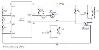
The values of the LM56 thermostat project circuit diagram for resistors R1, R2, and R3 at the travel points VT1 and VT2 can be determined using the following equations. This electronic circuit thermostat with the IC LM56 serves as...
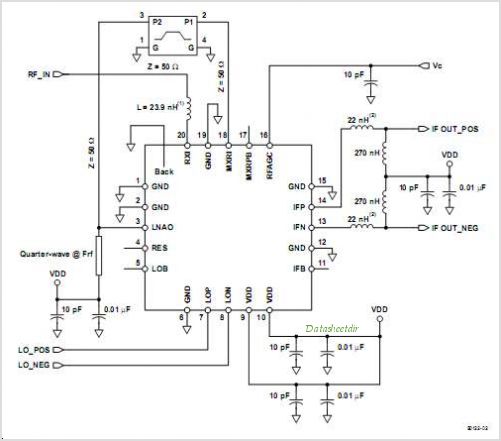
The TRF1400 VHF/UHF RZ ASK remote control receiver is specifically designed for RZ ASK (return-to-zero amplitude-shift keyed) communications systems operating in the 200-MHz to 450-MHz band. This device is targeted for use in automotive and home security systems, garage...
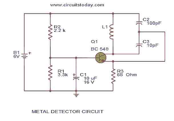
This is the circuit diagram of a low cost metal detector using a single transistor circuit and an old pocket radio. This is nothing but a Colpitts oscillator working in the medium band frequency and a radio tuned to...
This circuit is a simple buzzer circuit known as a novel buzzer. It utilizes a relay in series with a small audio transformer and a speaker. The relay will activate the circuit. The novel buzzer circuit operates by employing a...
The metal detector circuit comprises an oscillator and a sound-light alarm circuit. The oscillator circuit includes an inductor (L), a capacitor (C1), a sensor switch integrated circuit (IC1) that integrates the oscillator, detector, comparator circuit, and peripheral components. The...
Below is a block diagram of modern automated systems that incorporate closed-loop feedback for motion control. They typically include a servo system that consists of various components. Automated systems utilizing closed-loop feedback mechanisms are designed to enhance precision and responsiveness...
Warning: include(partials/cookie-banner.php): Failed to open stream: Permission denied in /var/www/html/nextgr/view-circuit.php on line 713
Warning: include(): Failed opening 'partials/cookie-banner.php' for inclusion (include_path='.:/usr/share/php') in /var/www/html/nextgr/view-circuit.php on line 713